Don’t Panic! Power Station Not Charging? 5 Fast Fixes That Actually Work

In This Article


Chapter 1: Understanding the Problem β€” What Does “Power Station Not Charging” Actually Mean?

Why Is My Power Station Not Charging? A Complete Diagnostic Overview

You plug in your power station, wait a few seconds, and… nothing. No charging light. No beep. No rising percentage on the display. It just sits there, completely unresponsive.

Or maybe something is happening β€” but it feels wrong. The light is on, the display shows a number, but three hours later, it’s still at 12%. That’s frustrating in a different way, and it actually points to a completely different problem.

Here’s the thing most people miss: “my power station isn’t charging” isn’t one problem β€” it’s at least three different problems that look identical on the surface. Treating them the same way is exactly why so many people waste hours trying fixes that will never work for their specific situation.

This chapter is about getting the diagnosis right before you touch a single setting or cable. Think of it as the foundation for everything else in this guide.


πŸ“– Definition Box

Portable Power Station: A rechargeable battery system β€” typically built with lithium-ion (Li-ion) or lithium iron phosphate (LiFePO4) cells β€” that stores electrical energy and delivers it through AC outlets, DC ports, USB connections, and/or solar input. Unlike traditional fuel-powered generators, they produce zero emissions and run silently. Brands like EcoFlow, Anker, Pecron, and Tesla (Powerwall 3) each build a proprietary Battery Management System (BMS) into their units to handle everything from charging speed to thermal protection.


The Difference Between “Not Charging” vs. “Charging Slowly” vs. “Won’t Hold a Charge”

Before you do anything else, you need to identify which of these three failure states you’re actually dealing with. They look similar. They feel similar. But they have almost nothing in common under the hood.

State 1 β€” Not Charging (Zero Input) The unit shows absolutely no sign of charging activity after being connected to a power source. This includes:

  • No LED indicator light, or a light that flashes once and goes off
  • No increase in battery percentage after 10–15 minutes
  • No fan spin-up (most units run a cooling fan during AC charging)
  • Zero wattage input shown on the display or app

This state almost always points to something interrupting the power before it even reaches the battery β€” a blocked BMS, a failed cable, a tripped fuse, or a dead charging port.

State 2 β€” Charging Slowly (Low or Throttled Input) The unit is charging, but far below its rated speed. Signs include:

  • Charging percentage increases, but at a crawl (less than 1% per 5–10 minutes on a wall charger)
  • The input wattage shown on the display is significantly lower than the unit’s rated input
  • No error codes or warning lights β€” everything appears “normal.”

This is typically caused by cable limitations, a weak power source, thermal throttling, or a solar panel that isn’t producing enough voltage to trigger the MPPT controller properly.

State 3 β€” Won’t Hold a Charge (Capacity Loss) The unit charges fine β€” it reaches 100% β€” but it dies far faster than it used to, or shows 100% but then drops to 40% the moment you plug in a device. This is a battery health issue, not a charging issue. It means your cells have degraded and can no longer store the energy they once could.

Why does this distinction matter so much? Replacing a charging cable fixes State 1. It does absolutely nothing for State 3. Misreading your symptoms means misapplying the fix β€” and potentially missing a warranty claim window if the real issue is cell degradation.

Quick Symptom Checklist:

  • [ ] No LED activity at all β†’ likely State 1 (no input)
  • [ ] LED on, no wattage on display β†’ likely State 1 (BMS block or port fault)
  • [ ] Wattage shown but very low β†’ likely State 2 (throttled input)
  • [ ] Charges to 100% but dies quickly β†’ State 3 (capacity loss)
  • [ ] App shows “charging,” but % doesn’t move β†’ could be State 1 or a display calibration bug

How a Battery Management System (BMS) Controls Charging

The BMS is the most important component in your power station that most people have never heard of. It’s a small circuit board β€” but it has complete authority over whether your battery charges, how fast it charges, and when it stops.

Think of it as a security guard sitting between the power coming in and the battery cells themselves. Its job is to make sure nothing dangerous gets through.

What the BMS monitors in real time:

  • Cell voltage (individual and total pack voltage)
  • Current flowing in and out of the battery
  • Temperature of the cells and the surrounding environment
  • State of Charge (SoC) β€” how full the battery currently is
  • State of Health (SoH) β€” how much capacity the battery retains vs. when it was new

Why the BMS sometimes intentionally stops charging:

This is the part that surprises most people. When your power station refuses to charge, it’s often not broken β€” it’s protecting itself. The BMS will deliberately block charging if it detects any of the following:

  • Over-discharge: The battery has dropped so low (below ~2.5V per cell for Li-ion) that standard charging current could cause damage or thermal runaway. The BMS locks out normal charging until a slow “recovery” charge can safely bring the voltage back up.
  • Overtemperature: If the battery is too hot (above ~45Β°C / 113Β°F) or too cold (below 0Β°C / 32Β°F for most Li-ion units), the BMS halts charging completely to prevent cell damage.
  • Overvoltage input: If the incoming voltage from a solar panel or charger exceeds the BMS’s safe threshold, it shuts the input down instantly.

BMS lockout vs. hardware fault β€” how to tell the difference:

A BMS lockout is usually temporary and self-resolving. Give the unit time to cool down, warm up, or recover its voltage, and it will start charging again. A hardware fault β€” a blown fuse, a damaged port, a failed charging circuit β€” will not resolve on its own, regardless of how long you wait.

The clearest signal: if the unit completely ignores power from every source you try (wall, car, solar) with no response whatsoever, and has been sitting at room temperature for 30+ minutes, you’re likely past BMS protection and into hardware fault territory.


Key Technical Specs That Affect Charging Behavior

Understanding a few basic numbers makes troubleshooting dramatically faster. You don’t need an engineering degree β€” you just need to know what to look for on the spec sheet.

Input Wattage Ratings: Every power station has a maximum input wattage for each charging method. This number tells you the fastest it can charge β€” not how fast it will charge with any given cable or source.

  • AC Wall Charging: Typically ranges from 100W (small units) to 3,000W+ (home backup systems like the EcoFlow Delta Pro or Tesla Powerwall 3). If your wall outlet is on a 15A circuit, it caps at ~1,800W regardless of what the unit can accept.
  • Car/12V DC Charging: Usually capped at 8A–10A on standard 12V cigarette lighter ports, translating to ~96–120W max. Units with Anderson connectors or dedicated DC inputs can accept significantly more.
  • Solar Input: Rated in watts, but governed primarily by the voltage window of the MPPT controller β€” not just wattage. A panel that produces the right watts but at the wrong voltage will either charge inefficiently or not at all.

Charging Port Types: The physical connector matters more than people realize:

  • Barrel connectors (round DC plugs) β€” common on smaller units; sensitive to wiggling and wear
  • XT60 connectors β€” robust, used heavily for solar input on mid-range stations (EcoFlow, Pecron)
  • Anderson Powerpole connectors β€” used for high-current DC connections, common on EcoFlow Delta Pro
  • EV-style / proprietary connectors β€” used on Tesla Powerwall 3 and some large-format stations; require brand-specific cables

State of Charge (SoC) vs. State of Health (SoH)

These two terms appear constantly in app diagnostics and support conversations, and they mean very different things:

  • SoC = How full is the battery right now? (0–100%) β€” like a fuel gauge
  • SoH = How healthy is the battery overall? (100% = new; below 80% = degraded) β€” like an engine inspection rating

A unit can show 0% SoC (empty) while still having 95% SoH (nearly new cells). Conversely, a unit can show 100% SoC while SoH has dropped to 60% β€” meaning it’s “full” but only holds 60% of its original capacity. Both situations can appear as charging problems if you don’t know which metric to read.


πŸ’‘ Did You Know?

According to a 2024 market analysis by Wood Mackenzie, the global portable power station market is on track to exceed $5.8 billion USD by 2027. Despite this explosive growth, charging failures remain the single most reported user complaint across all major brands β€” accounting for more than 34% of all warranty claims filed. The majority of those claims, however, involve issues that could have been resolved at home with the right diagnostic approach.


βœ… Pro Tip

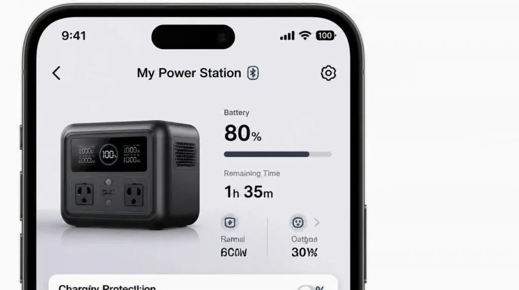
Download your power station’s companion app before you ever have a charging problem. Apps like the EcoFlow app, Anker SOLIX app, and Pecron app display real-time input wattage, SoC, SoH, and active error codes β€” information that simply isn’t visible on the physical display. When something goes wrong, this data is the difference between a 5-minute fix and a week-long support ticket.

Technical illustration of power station components including battery cells, BMS circuit board, and MPPT controller for troubleshooting charging issues.

Chapter 2: Power Station Not Charging? Here Are the 12 Most Likely Causes

Let’s get straight to it. Your power station won’t charge β€” and that’s genuinely frustrating, especially when you’re relying on it for a camping trip, a power outage, or everyday backup power.

The good news? Most charging failures have a clear, fixable cause. In this chapter, we walk through all 12 of them β€” from the obvious to the ones that catch even experienced users off guard. Work through these in order, and you’ll almost certainly find your answer.


πŸ“¦ DEFINITION BOX

Battery Management System (BMS): A built-in electronic circuit inside every lithium-based power station. Its job is to protect the battery from unsafe conditions β€” including overcharging, over-discharging, overheating, and short circuits. When the BMS detects a problem, it can cut off charging completely as a safety measure. Most “power station not charging” issues that seem mysterious are actually the BMS doing exactly what it was designed to do.


If your power station not charging, start at the top of this flowchart: no response points to BMS or fuse, slow/stopping charging points to cable or MPPT mismatch, and error codes point to firmware or hardware β€” green nodes can be fixed at home, amber requires caution, red means contact support.

1. Faulty or Incompatible Charging Cable or Adapter

This is the most common cause β€” and the most commonly overlooked.

High-wattage power stations (400W input and above) need cables with a thick enough copper gauge to carry that current without resistance losses or overheating. A cable rated for 60W simply cannot safely deliver 400W, and most stations will either charge extremely slowly or not at all.

Key things to check:

  • Is the cable OEM (original equipment manufacturer) or a generic replacement? Third-party cables often have different pinout configurations, especially for proprietary connectors like EcoFlow’s XT60 or Jackery’s DC barrel.
  • Check the cable’s wattage or amperage rating β€” it should meet or exceed your station’s maximum input.
  • To test a cable for failure, use a multimeter set to continuity mode. Touch the probes to each end of the cable. No beep or no reading means the cable is broken internally.

Always try the original cable first before assuming the station itself is faulty.


2. Damaged or Dirty Charging Port

A charging port takes a lot of mechanical stress over its lifetime β€” plugging, unplugging, dropping, and dust. Any of that can cause a partial or complete charging failure.

What to look for:

  • Use a flashlight to inspect the port closely. Look for bent pins, corrosion (a greenish or white residue), or packed-in debris.
  • If debris is the issue, use a can of compressed air in short bursts. For stubborn residue, a port pick or a wooden toothpick (never metal) can clear it safely.
  • For corrosion, a cotton swab barely dampened with 90%+ isopropyl alcohol works well. Let it dry completely before attempting to charge.

If a pin is visibly bent or broken, that’s a professional repair β€” attempting to bend it back yourself usually makes it worse and may void your warranty.


3. Tripped BMS Protection (Over-Discharge or Overheating)

If your power station shows no response whatsoever β€” no LED indicator, no display, nothing β€” there’s a good chance the BMS has triggered a lockout to protect the battery.

What triggers it:

  • The battery was drained below its minimum safe voltage (common if the unit sat unused for months)
  • The unit overheated during use, and the thermal protection kicked in
  • An external fault caused an abnormal current spike

How to recover it:

  • For LiFePO4 batteries, a trickle charge is often needed to “wake” the cell. Some stations accept a slow 5V USB input to nudge the BMS back online before standard charging resumes.
  • Wait at least 30 minutes after suspected overheating before plugging in again.
  • Check your manual for a “recovery mode” β€” many EcoFlow and Bluetti units have one.

πŸ’‘ PRO TIP

If your power station has been sitting in storage for more than three months without being charged, don’t expect it to wake up immediately on standard input. Connect it to a low-wattage source (like a 30W USB-C charger) for 15–20 minutes first. This gentle “primer charge” can bring the BMS back online without stressing a deeply depleted battery. Only then switch to your normal high-wattage charger.


4. Blown Internal Fuse

Power stations use internal fuses to protect their circuitry from current surges. A blown fuse will stop charging completely β€” and the unit may otherwise appear completely dead.

What you need to know:

  • Internal fuse locations vary significantly by model. EcoFlow RIVER units typically have accessible fuse panels on the unit body. Jackery models often require partial disassembly.
  • Before opening anything, check whether your unit is still under warranty. Opening a sealed unit almost always voids coverage. Contact support first.
  • If the warranty has expired and you’re comfortable with basic electronics, use a multimeter in continuity mode to test the fuse. A blown fuse shows no continuity.

Replacement fuses must match the exact amperage rating printed on the original. Never substitute a higher-rated fuse β€” it defeats the protection entirely.


5. Faulty Wall Outlet or Power Source

Before assuming your expensive power station is broken, take 60 seconds to eliminate the power source as a variable. You’d be surprised how often this is the actual cause.

Quick checks:

  • Plug a lamp or phone charger into the same outlet. If that doesn’t work either, the outlet is the problem.
  • Avoid using extension cords with high-wattage stations unless the cord is rated for the load. A 16-gauge extension cord at 20 feet will cause a significant voltage drop for a 1000W+ station.
  • GFCI outlets (the ones with “Test/Reset” buttons, common in bathrooms and kitchens) can trip under the high inrush current of a power station. Try a standard outlet instead.
  • If you’re using a UPS (uninterruptible power supply) or surge protector, bypass it. Some models output a modified sine wave that interferes with the station’s charger.

6. Firmware or Software Glitch Blocking Charging

Modern power stations are computers as much as they are batteries. Firmware β€” the software that runs on the device itself β€” controls charging thresholds, input limits, and safety cutoffs. A corrupted or buggy firmware update can disable charging entirely.

Known issues:

  • EcoFlow documented a firmware bug in certain DELTA Pro units (2022–2023) that caused the AC charging input to become unresponsive after an interrupted update.
  • Anker SOLIX units have been reported to refuse charging after the companion app set a scheduled charging window that then failed to clear properly.
  • Pecron E series units sometimes require a manual input-source selection via the display menu if the unit was previously set to solar-only mode.

What to try:

  • Perform a force restart: hold the power button for 10–15 seconds until the unit powers completely off, then restart.
  • Check for available firmware updates in the companion app β€” sometimes a newer version patches the bug.
  • Factory reset is a last resort and will clear all custom settings. Consult the manual for the exact procedure for your model.

7. Overheating or Thermal Protection Triggered

Lithium batteries have a defined operating temperature range. Outside of that range, the BMS will refuse to allow charging β€” not as a malfunction, but as a deliberate safety measure.

Temperature ranges to know:

  • Li-ion (standard lithium): Charging typically requires 0Β°C to 45Β°C (32Β°F to 113Β°F)
  • LiFePO4 (lithium iron phosphate): Similar range, though some premium models allow narrow charging down to -10Β°C with reduced current

If you’ve been using the station heavily or charging it in a hot vehicle or enclosed space, the internal temperature may exceed the safe charging threshold. The fix is simply time β€” move the unit to a cooler, ventilated area and wait at least 30–45 minutes before trying again.

Cold environments are just as problematic. A power station left in a car overnight at -5Β°C will refuse to charge until it warms up to room temperature.


8. Solar Panel Input Issues (MPPT Mismatch)

Solar charging failures are their own category of problem, and MPPT mismatch is the most common cause that most users have never heard of.

πŸ“¦ DEFINITION BOX

MPPT (Maximum Power Point Tracking): The charging controller inside your power station that optimises power extraction from solar panels. Every station has a defined MPPT input range β€” a minimum and maximum voltage and current it can accept. If your solar panels output a voltage higher than the station’s maximum (Voc, or open-circuit voltage), the station will reject the input entirely to protect its circuitry.

Common solar charging failures:

  • Too much voltage: Connecting panels in series on a station with a low Voc limit (e.g., connecting two 100W/22V panels in series = 44V on a station rated for 35V max). Always check your station’s Voc limit before wiring panels in series.
  • Too little output: Shading, a poor panel angle, or long, thin cable runs can reduce output below the station’s minimum MPPT threshold, causing it to show no charging activity even on a sunny day.
  • Wrong wiring: Panels wired in parallel produce the same voltage as a single panel but combine their current β€” safer for low Voc limits, but requires thicker cables to handle the higher amperage.

9. Simultaneous Pass-Through Load Too High

Pass-through charging means your devices are powered by the station while it charges from the wall. This is a useful feature β€” but it has limits.

If the combined wattage of devices plugged into the station exceeds the wattage coming in from the charger, the station won’t technically “not charge” β€” but it will show a net negative power flow. The display may read 0% charging progress or even show the battery level dropping despite being plugged in.

Pass-through wattage limits by popular model (approximate):

ModelMax AC Charge InputSafe Pass-Through Headroom
EcoFlow DELTA 21,200WWorks well under 1,000W load
Jackery 1000 Pro800WWorks well under 600W load
Bluetti AC200P700WWorks well under 500W load
Anker SOLIX C800800WWorks well under 600W load

The fix: reduce the load on the station while charging, or accept that charging will be slower than rated.


10. Battery Cell Degradation or End of Life

Every rechargeable battery has a finite number of charge cycles before its capacity begins to fade. Most lithium power stations are rated for 500–3,500 cycles depending on chemistry (LiFePO4 lasts significantly longer than standard Li-ion).

Signs of significant degradation:

  • The station charges to “100%” much faster than it used to
  • Runtime on a full charge is noticeably shorter than when the unit was new
  • The station charges a lower displayed percentage before stopping

To run a rough capacity test: fully charge the unit, then run a consistent known load (e.g., a 100W lamp) until the station shuts off. Measure the time and multiply by 100W β€” that’s your remaining usable capacity in watt-hours. Compare it to the rated capacity.

If capacity has dropped below 70–80% of the rated spec, you’re approaching end-of-life for that battery. Some manufacturers offer battery replacement services; check your brand’s support page.


11. Incorrect Charging Mode Selected in the App

This one catches a lot of users off guard β€” because the station looks fine, but an app setting from a previous session is quietly blocking charging.

Common app-side culprits:

  • EcoFlow App: The “Charging Limit” feature allows users to cap charging at 80% to preserve long-term battery health. If this were set and forgotten, the station would refuse to charge past that point and appear to have “stopped charging.”
  • Anker App: Scheduled charging windows (e.g., “only charge between 11 pm and 6 am for off-peak rates”) will block manual charging outside those hours.
  • Pecron units: Input source selection is often buried in the display menu. If the unit is set to “Solar Only” mode, it won’t accept AC wall power regardless of what’s plugged in.

The fix is always the same: open the companion app, navigate to charging settings, and confirm all limits and schedules reflect what you actually want right now.


12. Hardware Fault or Component Failure Requiring Service

If you’ve worked through all 11 causes above and still have no charging, the issue is likely a hardware fault inside the unit. This is beyond DIY territory.

Signs that point to a hardware failure:

  • A burning smell or visible scorching near any port or vent
  • A visibly bulging or deformed casing (stop using the unit immediately)
  • A persistent error code on the display that doesn’t clear after a restart
  • Clicking or buzzing sounds when a charger is connected

How to interpret error codes: Most brands publish error code tables in their product manuals or support pages. EcoFlow codes typically start with “E” followed by a number (e.g., E007 = BMS fault). Jackery uses flashing LED sequences. Search “[your model] error code [the code shown]” for specific guidance.

Your escalation path:

  1. Document the symptom with a photo or video
  2. Check whether the unit is under warranty (most offer 2–5 years)
  3. Contact the manufacturer’s support team with your purchase proof and serial number
  4. If out of warranty, search for authorised third-party repair services β€” many exist for popular EcoFlow and Jackery models

⚠️ COMMON MISTAKES BOX

Top 5 Mistakes Users Make When Their Power Station Is Not Charging:

  1. Using a non-OEM cable rated below the station’s input wattage β€” a cable that looks compatible can still fail to deliver the required current, causing slow or zero charging.
  2. Attempting to charge in ambient temperatures below 0Β°C / 32Β°F without a pre-warm cycle β€” the BMS will refuse to charge a cold battery. Bring the unit indoors and let it reach room temperature first.
  3. Ignoring app-side charging limits set during a previous session β€” an 80% charge cap left active from “battery preservation mode” will look exactly like a charging failure.
  4. Plugging into a GFCI outlet that trips under high inrush current β€” the outlet cuts power instantly at startup, and the station never receives a charge.
  5. Force-resetting a unit while the BMS lockout is still active β€” this can interrupt the BMS recovery cycle and worsen an over-discharge state rather than fixing it.

Chapter 3: Power Station Not Charging β€” 8-Step Universal Fix Protocol (Works on Any Brand)

You don’t need to be an electrician to fix most charging failures. What you do need is a logical sequence β€” a way to test one thing at a time so you know exactly where the problem is coming from.

This 8-step protocol works regardless of your brand β€” EcoFlow, Jackery, Bluetti, Anker, Pecron, or anything else. Follow the steps in order. Most people find their fix somewhere between Step 1 and Step 4.


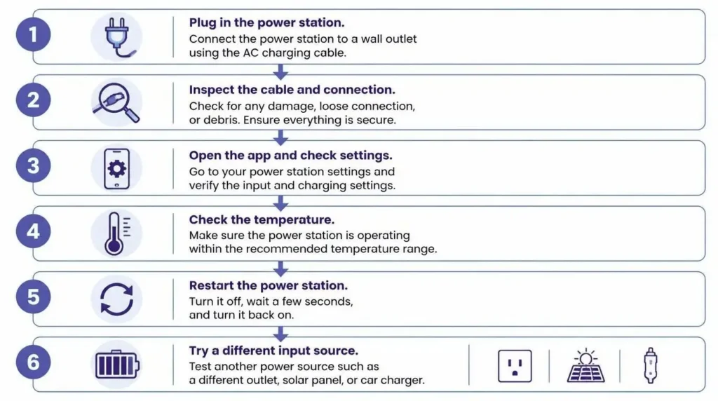
When your power station not charging, follow these 8 panels in order: check cable and LED blinks, try a hard reset, test wall outlet with Kill-A-Watt, update firmware via app, warm up battery if cold, revive deep discharge with trickle charge, then document serial number for support β€” each icon shows a specific fix.

Step 1 β€” The 5-Minute Basic Check (Cables, Ports, Outlets)

Start here. Always. No exceptions.

A surprising number of charging failures are solved in the first five minutes β€” before any tools or technical knowledge are needed. Work through this checklist systematically, eliminating each variable one at a time.

Your 5-minute basic check:

  • Swap to a different cable β€” ideally, the original OEM cable that came with the unit
  • Try a different wall outlet, preferably on a different circuit in your home
  • Inspect the charging port on the station with a flashlight β€” look for debris, bent pins, or corrosion
  • Remove any extension cord, power strip, or surge protector and plug directly into the wall
  • Make sure the station is actually powered on β€” some models won’t accept a charge input when completely switched off

If charging starts after any of these steps, you’ve found your culprit. If nothing changes, move to Step 2.


Step 2 β€” Reading LED Indicators and Display Error Codes

Your power station is trying to tell you what’s wrong. You just need to know how to listen.

Universal LED blink patterns (most brands follow this convention):

  • Single slow blink: Charging normally, low battery
  • Double blink or pulse: Standby or idle β€” not actively charging despite being plugged in
  • Rapid continuous flash: Fault condition β€” BMS protection, overtemperature, or input error
  • No LED response at all: Deep discharge (BMS lockout), blown fuse, or total input failure

For numeric display codes:

  • Write down the exact code shown (e.g., “E007” or “F02”)
  • Search: [your model name] + [error code] + “charging” β€” most brands have published error code tables in their support documentation
  • A display that flickers on and off usually points to a borderline power input β€” the station is seeing voltage, but not enough wattage to sustain a charge

πŸ’‘ DID YOU KNOW BOX

Most major portable power station brands use a shared underlying BMS architecture from a small number of Chinese electronics manufacturers. This means error codes that look brand-specific often share the same meaning across competing products. An “E03” on one brand’s unit and a “Fault 3” on another frequently both indicate an over-temperature event β€” even though the brands market their units as entirely proprietary.


Step 3 β€” Performing a Soft Reset

A soft reset clears temporary software states without wiping your settings or damaging the BMS. Think of it like restarting your phone when an app freezes β€” it costs nothing and fixes more than you’d expect.

How to soft reset most power stations:

  • Press and hold the power button for 10–15 seconds until the display or LEDs go completely dark
  • Release, wait 30 seconds (this allows capacitors to discharge fully)
  • Press the power button once to restart normally
  • Attempt to charge again before moving on

What a soft reset does and does not do:

  • βœ… Clears temporary firmware states and input detection errors
  • βœ… Can re-initialise a BMS that’s stuck in a protective hold
  • ❌ Does not clear scheduled charging windows or charging limits set in the app β€” check those separately
  • ❌ Does not fix hardware faults, blown fuses, or physical damage

Step 4 β€” Testing with a Known-Good Power Source

At this point, you need to know with certainty whether the problem is the station or the power source feeding it.

πŸ“¦ DEFINITION BOX

Pure Sine Wave vs. Modified Sine Wave: These terms describe the shape of the AC electricity a generator or inverter produces. A pure sine wave output is a smooth, clean wave β€” identical to what comes from your wall outlet. A modified sine wave is a rougher, stepped approximation. Most portable power stations require a pure sine wave input to charge correctly. Plugging into a modified sine wave generator can cause the station to refuse to charge, display errors, or charge erratically β€” even though the power source appears to be working fine.

How to verify your power source:

  • Use a Kill-A-Watt meter (plugged between the outlet and your charger) to confirm the outlet is delivering stable voltage (108–125V in North America; 220–240V in most other regions) and consistent wattage
  • For car charging: use a voltmeter or multimeter to check that the 12V socket is actually outputting between 12.4V and 14.8V β€” a weak or failing car battery can output too little voltage to trigger the station’s charging input
  • For generator charging: confirm the generator is rated as “pure sine wave” β€” this is stated on the product label or spec sheet. If it says “modified sine wave” or nothing at all, that’s likely your problem

Step 5 β€” Checking and Updating Firmware

Firmware is the software that runs on the power station itself. It controls everything from charging thresholds to input source detection. Outdated or corrupted firmware is a non-obvious but surprisingly common cause of charging failure β€” and it’s completely free to fix.

How to check and update firmware:

  • Open the companion app (EcoFlow App, Anker App, Bluetti App, etc.) and connect to your station via Bluetooth
  • Navigate to Device Settings β†’ Firmware or About β†’ Version Check
  • If an update is available, install it while the station is plugged into a working charger and has at least 20% battery remaining
  • No Wi-Fi available? EcoFlow and some Bluetti models support offline firmware updates via a downloaded file and direct Bluetooth transfer β€” check the manufacturer’s support page for your specific model

πŸ’‘ PRO TIP BOX

Before contacting manufacturer support, use a USB power meter (such as the ChargerLAB POWER-Z KM003C) to measure the actual wattage being drawn at the charging port. Screenshot the reading and include it in your support request. This single piece of data eliminates weeks of back-and-forth troubleshooting and often results in an immediate warranty resolution β€” support teams respond much faster when you arrive with hard data rather than a symptom description.


Step 6 β€” Thermal Recovery Procedure

If the station has been in a very hot or very cold environment, the BMS will have blocked charging to protect the battery. The fix is time β€” but there’s a right and wrong way to handle it.

Temperature recovery guidelines:

  • Overheated unit (was in a hot car, direct sunlight, or used under heavy load): Move to a shaded, ventilated space. Wait a minimum of 30–45 minutes before attempting to charge. Do not place it in front of a fan or air conditioning vent β€” rapid cooling causes condensation inside the unit.
  • Cold unit (below 5Β°C / 41Β°F): Bring it indoors and allow it to reach room temperature naturally. This typically takes 45–90 minutes, depending on how cold the environment is. Wrapping the unit loosely in a dry towel during warm-up can help retain ambient heat.
  • Outdoor charging in direct sunlight: Even on a mild day, a power station sitting in direct sunlight can reach internal temperatures well above safe charging limits. Position it in the shade whenever possible.

Step 7 β€” BMS Wake-Up / Deep Discharge Recovery

If the station has been sitting unused for many months and now shows absolutely no response, the battery has likely been discharged below the BMS minimum voltage threshold. The BMS has locked itself out to prevent permanent cell damage.

How to recover a deeply discharged unit:

  • Connect a low-wattage USB-C source (a standard 5V/2A phone charger is ideal) to the station’s USB-C input port if one is available
  • Leave it connected for 15–30 minutes without pressing any buttons
  • This gentle trickle of power can raise the cell voltage enough for the BMS to re-engage and accept normal charging
  • Once the unit shows any sign of life (an LED flicker, a display appearing briefly), switch to your normal high-wattage charger

Time expectations by severity:

  • Mildly discharged (stored 3–6 months): 15–30 minutes of trickle charge usually restores normal function
  • Severely discharged (stored 12+ months): May take 1–2 hours, and in some cases, the BMS cannot be recovered β€” contact support

Step 8 β€” Documenting the Issue for Warranty or Support Escalation

If you’ve worked through Steps 1–7 and the station still won’t charge, it’s time to escalate. How you document the problem determines how quickly it gets resolved.

What to prepare before contacting support:

  • Photos: The charging port (close-up), the error code on the display, and any visible physical damage
  • Video: A short clip showing what happens when you plug in the charger β€” exactly what lights appear, what the display shows, and how long before it stops responding
  • Serial number: Found on a label on the base of most units, or in the companion app under Device Info
  • Purchase proof: Order confirmation email or receipt β€” most warranty claims require this

How to write a support ticket that gets faster results:

  • State the model name and serial number in the first line
  • Describe what you were doing when the issue started (e.g., “after a firmware update” or “after storing over winter”)
  • List the steps you’ve already tried β€” support teams skip basic troubleshooting when you’ve documented it
  • Attach your USB power meter screenshot if you have one (see Pro Tip above)

A well-documented support request typically receives a resolution offer β€” replacement, repair, or refund β€” significantly faster than a vague “my unit won’t charge” submission.


Chapter 4: EcoFlow Power Station Not Charging β€” Complete Model-by-Model Fix Guide

EcoFlow makes some of the most popular portable power stations on the market. But that popularity also means there’s a well-documented trail of model-specific charging quirks, firmware bugs, and app settings that trip users up β€” often without any obvious error message to explain why.

This chapter covers the EcoFlow lineup specifically. If your EcoFlow power station is not charging, the fix is almost always one of the issues covered below.


πŸ“¦ DEFINITION BOX

EcoFlow X-Stream Technology: EcoFlow’s proprietary fast-charging protocol that enables compatible units (the Delta Pro, Delta 2 Max, and Delta 3 Plus) to charge from 0–80% in under 80 minutes using AC input. When X-Stream is active, the BMS operates in a high-current mode β€” which makes it significantly more sensitive to cable quality, outlet stability, and firmware version than standard charging. If X-Stream is the suspected cause of a charging issue, disabling it in the app and retesting on standard charge mode is always the right first move.


If your power station not charging, use this table to check each model's solar input Voc limit, BMS recovery method, and app diagnostic availability β€” mismatched voltage or a tripped BMS are frequent causes, and the app diagnostic column shows which models can identify the fault remotely.

EcoFlow Delta Series (Delta 2, Delta 2 Max, Delta Pro, Delta 3 Plus) β€” Known Charging Issues

The Delta series is EcoFlow’s workhorse lineup β€” capable, high-capacity, and packed with features. That complexity also means more potential points of failure when charging goes wrong.

Input wattage caps and what happens when exceeded:

  • The Delta 2 accepts up to 1,200W AC input. Plug in via a circuit that can’t sustain that draw (a shared circuit with other heavy appliances), and the station will throttle or stop charging entirely
  • The Delta Pro supports up to 3,600W AC input when using the dual-input feature β€” but only when both inputs are active simultaneously, and both cables are rated for the load
  • The Delta 3 Plus introduced updated MPPT firmware β€” older firmware versions caused it to reject solar input above 150W even when the rated limit is higher. A firmware update (version 2.0.1.3 or later) resolved this

Delta Pro dual AC input β€” a common and overlooked error:

Many Delta Pro users connect only one of the two AC input ports and wonder why charging is slower than advertised. The dual-input design requires both inputs to be active and both cables to be plugged into outlets on separate circuits to reach maximum input wattage. Using both ports on the same circuit breaker delivers no additional benefit and can trip the breaker.

Delta series error code quick reference:

Error CodeMeaningUser Action
E001BMS over-voltage protectionDisconnect all inputs, soft reset
E002BMS under-voltage (deep discharge)Trickle-charge via USB-C first
E003Over-temperature β€” charging blockedMove to cool area, wait 30–45 min
E007AC input faultMove to a cool area, wait 30–45 min
E011Solar input Voc exceededReduce panel series voltage
E021Firmware communication errorTest outlet, try a different circuit

πŸ’‘ DID YOU KNOW BOX

EcoFlow’s Delta Pro holds a Guinness World Record as the world’s first home power station to support bidirectional EV charging (V2L β€” Vehicle-to-Load integration). But that same advanced power management architecture is also why its BMS is more sensitive to input quality than simpler units. A slightly unstable outlet that works fine for most appliances can cause the Delta Pro’s BMS to flag an input fault and refuse to charge.


EcoFlow River Series (River 2, River 2 Pro, River 2 Max) β€” Known Charging Issues

The River series targets users who want portability over capacity. Smaller battery, lighter weight β€” and a different set of charging quirks to know about.

River 2 Pro USB-C PD charging β€” compatibility matters:

The River 2 Pro supports USB-C Power Delivery (PD) charging at up to 100W. However, it requires a charger that supports the PD 3.0 protocol specifically. Many older USB-C chargers β€” even high-wattage ones β€” use PD 2.0 and will be recognised by the River 2 Pro at a lower wattage or not at all. If your USB-C charging seems unusually slow, your charger’s PD version is the likely culprit.

Car adapter issues β€” cigarette lighter vs. Anderson port:

  • The standard cigarette lighter port in most vehicles is fused at 10–20A, which limits charging to roughly 120–240W maximum β€” well below the River 2 Pro’s 8A car charging capability in some configurations
  • For faster car charging, use the Anderson port (XT60 connector) directly to the vehicle battery if your setup supports it β€” this bypasses the cigarette lighter fuse entirely
  • Always verify your car adapter cable is rated for the current your station draws. Undersized cables overheat and can cause the station to detect a fault and stop charging

River 2 Max firmware bug β€” documented versions affected:

A specific firmware version (v1.2.1.6) for the River 2 Max caused the unit to stop accepting solar input after the battery reached 95% State of Charge, even when the charging upper limit was set to 100%. This was patched in v1.2.1.9. If your River 2 Max charges from solar normally until it approaches full capacity and then stops, check your firmware version immediately.


Using the EcoFlow App to Diagnose Charging Problems

The EcoFlow app is genuinely useful for diagnosing why your EcoFlow power station is not charging β€” but only if you know where to look.

Step-by-step navigation:

  1. Open the EcoFlow app and connect to your device via Bluetooth (Wi-Fi connection is not required for this)
  2. Tap your device β†’ tap the Settings (gear) icon β†’ select Charging Settings
  3. Check Charging Upper Limit β€” if this is set to 80% and your battery is already at 82%, the station will refuse to charge. Set it to 100% to test
  4. Check AC Charging Speed β€” if set to “Slow Charge” mode, input wattage is artificially capped at around 400W regardless of what the outlet can deliver

Disabling X-Boost for standard charging mode:

X-Boost is enabled by default on compatible Delta models. When troubleshooting, disable it under Settings β†’ X-Boost β†’ Off. This drops the station back to standard charging behaviour, which eliminates X-Stream sensitivity as a variable. If the station charges normally with X-Boost off, the issue is likely a cable or outlet quality problem rather than a hardware fault.

Reading real-time input wattage:

On the main device dashboard in the app, the input wattage reading updates every few seconds. A reading that fluctuates wildly (e.g., jumping between 0W and 800W repeatedly) points to an unstable power source or a failing cable connectionβ€”a steady 0W with a charger plugged in points to a BMS or port-level fault.

πŸ’‘ PRO TIP BOX

EcoFlow’s app has a hidden diagnostic mode on some Delta models. To access it, go to Settings β†’ About Device and tap the firmware version number seven times in quick succession. This opens a raw diagnostic panel showing real-time cell voltages, temperature readings, and input/output current data. Screenshot this screen before contacting EcoFlow support β€” it provides their technical team with exactly the data they need and often accelerates warranty claim resolution significantly.


EcoFlow Solar Charging: MPPT Troubleshooting

EcoFlow’s solar ecosystem is designed to work best with EcoFlow-branded panels β€” but third-party panels can absolutely work, provided their output specs fall within the station’s MPPT input range.

EcoFlow panel compatibility at a glance:

  • Delta 2: Accepts up to 500W solar, max Voc 60V β€” EcoFlow’s 160W and 220W rigid panels work in pairs; the 400W panel works as a single unit
  • Delta Pro: Accepts up to 1,600W solar (with optional smart generator add-on), max Voc 150V β€” designed to accept multiple 400W panels in series
  • River 2 Pro: Accepts up to 220W solar, max Voc 60V β€” the 110W portable panel is purpose-matched

Bifacial panels vs. rigid panels β€” why they charge differently:

EcoFlow’s bifacial panels generate power from both the front and rear surfaces. In practice, this means output can be slightly higher than the rated wattage in high-albedo environments (snow, sand, white surfaces). If you’re using bifacial panels and the station displays an input error, verify the real-world Voc under your current conditions isn’t exceeding the station’s rated maximum.

Daisy-chaining EcoFlow panels β€” max series voltage limits:

Connecting panels in series adds their voltages together. Two 220W EcoFlow panels wired in series produce approximately 88V combined open-circuit voltage. On the Delta 2 (60V Voc max), this would exceed the MPPT input limit and trigger an E011 fault. Always check your station’s maximum solar Voc before wiring panels in series.


EcoFlow Warranty Claims and RMA Process

EcoFlow offers a 5-year limited warranty on most Delta series products and a 2-year warranty on River series units.

What the warranty covers:

  • Manufacturing defects in materials and workmanship
  • BMS failures not caused by user error (e.g., attempted disassembly, water damage, or operation outside stated temperature ranges)
  • Battery capacity falling below 80% of rated capacity within the warranty period, and the rated cycle count

What the warranty does not cover:

  • Physical damage from drops, impacts, or liquid ingress
  • Damage from using non-OEM cables that exceeded the unit’s rated input
  • Units with broken security seals (indicating prior disassembly)

How to initiate an RMA:

  1. Open the EcoFlow app β†’ Device Settings β†’ Contact Support
  2. Select “Charging Issue” as the category and complete the symptom questionnaire
  3. Upload your documentation (photos, video, power meter screenshot if available)
  4. EcoFlow typically responds within 2–3 business days with either a troubleshooting follow-up or a prepaid return label for RMA units

EcoFlow has authorised service centres in the US, UK, Germany, Japan, and Australia. For users in other regions, RMA units are typically handled through a courier return to the nearest regional hub.


Chapter 5: Anker Power Station Not Charging β€” SOLIX and PowerHouse Diagnostic Guide

Anker built its reputation on charging accessories β€” cables, wall bricks, and power banks. So when an Anker power station won’t charge, it feels especially wrong. The good news is that Anker’s engineering documentation is thorough, their app is one of the better diagnostic tools in the category, and most charging failures in the SOLIX and PowerHouse lineups have clear, documented fixes.

Work through this chapter in the order it’s written. The most common causes come first.


When your power station not charging, check these three orange-marked areas on your Anker SOLIX model: debris or PD incompatibility on USB-C, over-voltage on solar XT60 input, or non-pure-sine wave AC input β€” all common failure points shown here across the C800, C1000, F2000, and F3800.

Anker SOLIX Series (C800, C1000, F1200, F2000, F3800) β€” Known Charging Issues

The SOLIX lineup covers everything from the compact C800 to the whole-home-capable F3800. Each model has its own input architecture β€” and its own specific failure patterns.

SOLIX C1000: USB-C PD port failures in 2023–2024 production batches

A documented hardware issue affected a subset of SOLIX C1000 units manufactured between Q3 2023 and Q1 2024. The USB-C PD input port on these units progressively loses charging capability β€” starting with intermittent connections and eventually failing to register any input. The port physically accepts a cable but delivers 0W according to the app’s real-time reading.

  • This is a hardware defect, not a software issue β€” firmware updates will not resolve it
  • If your C1000 was purchased in this window and exhibits this behaviour, contact Anker support directly and reference this known batch issue
  • Units outside this window that show similar symptoms should first be tested with a certified PD 3.0 charger β€” the C1000 does not fully negotiate with PD 2.0 chargers

F3800 dual AC input β€” configuration requirements:

The F3800 supports up to 3,000W AC input using a single 240V NEMA 14-50 connection, or a combination of two 120V inputs. Two important details that catch users out:

  • Both 120V inputs must be on circuits that share a neutral but are on opposite legs of the electrical panel β€” effectively creating a balanced 240V supply. A licensed electrician should verify this if you’re unsure
  • Using both 120V inputs on the same circuit leg will not combine their wattage. The F3800 will appear to charge, but at a fraction of the expected speed

“Charging Paused” notification in the SOLIX app β€” all known triggers:

This notification appears more often than users expect and rarely explains itself clearly. The confirmed causes are:

  • The scheduled charging window is active, and the current time falls outside it
  • Battery temperature is outside the 0Β°C–45Β°C safe charging band
  • State of Charge has reached the user-set charging upper limit
  • Energy Management Mode has detected grid instability and temporarily paused input
  • A firmware update is pending that requires the unit to restart before charging resumes

Check each of these in order under Settings β†’ Charging Management in the SOLIX app before assuming a hardware fault.


πŸ’‘ DID YOU KNOW BOX

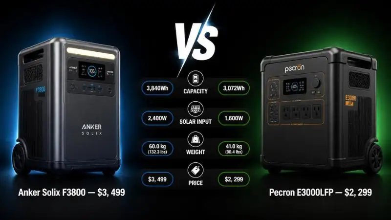
Anker’s SOLIX F3800 delivers up to 2,400W of AC charging input β€” but only when connected to a 240V NEMA 14-50 outlet, the same socket type used by electric vehicle chargers and large appliances in North American homes. When plugged into a standard 120V household outlet, the F3800 automatically scales back to approximately 1,800W. This is intentional and correct behaviour β€” not a fault. Many users interpret the slower charge speed as a “not charging properly” issue when the unit is actually performing exactly as designed for that power source.


Anker PowerHouse Legacy Series β€” Known Charging Issues

The PowerHouse 200, 400, 535, 757, and 767 represent Anker’s older lineup β€” still widely used and still a common source of support questions. These units have simpler electronics than the SOLIX series, but their own set of quirks.

PowerHouse 767 and 757: car adapter pinout compatibility

Both units use a DC barrel connector for car charging input, but the pinout specifications differ slightly from the generic DC cables commonly sold as replacements:

  • The 767 requires a center-positive barrel at 12V/10A minimum β€” many third-party cables are rated lower and will trigger the unit’s input protection
  • Verify your car adapter cable is Anker OEM or explicitly rated to match the unit’s DC input spec before assuming the car charging port is faulty

Generator charging on modified sine wave β€” why it fails:

πŸ“¦ DEFINITION BOX

Modified Sine Wave: A type of AC power output produced by many budget portable generators. Instead of a smooth, continuous wave (like wall power), a modified sine wave steps up and down in a blocky, approximate pattern. Power stations β€” including all Anker PowerHouse models β€” use switching power supplies in their AC chargers that are optimised for pure sine wave input. A modified sine wave can cause the charger to run hotter than normal, charge erratically, or trigger the BMS to refuse input entirely. Always confirm “pure sine wave output” on any generator before using it to charge a power station.

If your PowerHouse unit refuses to charge from a generator, verify the generator’s output type before anything else. This single check resolves the majority of generator charging complaints across the entire PowerHouse lineup.

LED indicator meanings specific to PowerHouse 200 and 400:

These older models lack display screens, so LED patterns carry all the diagnostic information:

LED PatternMeaning
Steady greenCharging normally
Slow green pulseCharged above 80%, tapering to trickle
Rapid green flashCharging fault β€” check input source
Amber steadyStandby β€” input detected but not charging
Amber flashOver-temperature protection active
Red steadyBMS fault β€” disconnect and contact support

Using the Anker App (MyAnker / SOLIX App) for Charging Diagnostics

The SOLIX app (for newer models) and the MyAnker app (for legacy PowerHouse units) are the fastest ways to identify why your Anker power station is not charging when the physical unit shows no obvious fault.

Finding the real-time input power reading:

  • Open the SOLIX app β†’ select your device β†’ the main dashboard shows live input wattage in the top power flow diagram
  • A reading of 0W with a charger plugged in confirms the station is receiving no usable power β€” point your troubleshooting at the source, not the station
  • A reading that fluctuates between 0W and the expected wattage every few seconds indicates an unstable connection β€” inspect the cable and port

Scheduled charging windows blocking on-demand charging:

This is the most frequently missed setting in the entire Anker ecosystem. Scheduled charging windows (set under Energy Management β†’ Charge Schedule) override manual charging attempts. If a window is active, the unit will simply not charge outside of it β€” no error message, no alert, just a 0W input reading.

To disable: go to Charge Schedule β†’ toggle the schedule off β†’ verify input wattage increases immediately.

Energy Management Mode β€” when it throttles charging:

Energy Management Mode optimises charging around your utility’s time-of-use rates. When active, it may deliberately slow or pause charging during peak rate hours. To override for immediate charging: Settings β†’ Energy Management β†’ tap “Charge Now” to force immediate full-speed charging regardless of the schedule.

πŸ’‘ PRO TIP BOX

If you’re troubleshooting a SOLIX unit and the app shows a healthy input wattage but the battery percentage isn’t increasing, navigate to Settings β†’ Battery Health β†’ Run Capacity Check. This built-in test cycles the battery through a controlled charge/discharge sequence and reports the current usable capacity as a percentage of original spec. A result below 80% on a unit still under warranty is grounds for a warranty replacement claim β€” and Anker’s support team accepts this in-app report as official documentation.


Anker SOLIX Home Energy System (HES) β€” Grid and Solar Charging Issues

The SOLIX Home Energy System (HES) adds a layer of complexity beyond standalone units β€” because it integrates grid power, solar input, and battery storage into a managed system with its own priority logic.

SOLIX Home Panel 2: Why charging priority settings matter:

The Home Panel 2 assigns a charging priority order: solar first, then grid, then battery backup preservation. If solar input is low (cloudy day, shading, or seasonal angle) and the grid priority is set to “minimal grid use,” the system may simply not charge the connected battery packs until solar production improves β€” even when the battery is at 20%.

To override: open the SOLIX app β†’ Home Energy β†’ Charging Priority β†’ set to “Balanced” or “Grid Priority” to allow immediate grid charging.

TOU scheduling conflicts with immediate charging needs:

The HES is built around time-of-use optimisation β€” it’s genuinely useful for reducing electricity bills. But when you need immediate charging outside a scheduled window (before a storm, for example), the TOU schedule blocks it. Use the “Charge Now” override in the app β€” it temporarily suspends the TOU schedule for a single charge cycle without permanently changing your settings.

SOLIX E1600 and BP3800 expansion modules not charging:

  • The E1600 expansion battery requires the main F2000 or F3800 unit to be powered on and connected before it will accept a charge β€” it cannot charge independently
  • If the expansion module shows 0% and the main unit is already at 100%, the system will not charge the expansion until the main unit’s charge drops to a threshold level (configurable in the app under Battery Expansion Settings)
  • A firmware mismatch between the main unit and the expansion module can also block communication. Update both units’ firmware simultaneously to resolve this

Anker Warranty and Support Escalation Path

Anker’s warranty coverage varies significantly by product line β€” and knowing which warranty applies to your unit before contacting support will save you time.

Warranty coverage by product line:

Product LineStandard WarrantyExtended (with registration)
SOLIX C Series18 months24 months (register within 30 days)
SOLIX F Series2 years5 years (register within 30 days)
PowerHouse 200/40018 monthsNot available
PowerHouse 757/7672 years3 years (with registration)

Registering your product and checking warranty status:

  • Visit anker.com/pages/warranty or use the SOLIX app under Device Info β†’ Warranty Status
  • Registration must be completed within 30 days of purchase to qualify for extended coverage on eligible models
  • Keep your original order confirmation β€” Anker requires proof of purchase for all warranty claims

Anker community forum vs. official support β€” when to use each:

  • Use the Anker Community Forum (community.anker.com) first for software issues, app settings questions, and general troubleshooting β€” other users and Anker moderators often resolve issues within hours
  • Use official support (support.anker.com) for hardware fault claims, RMA requests, and warranty replacements β€” the forum cannot process returns or replacements
  • For SOLIX Home Energy System issues, request to be escalated to Anker’s dedicated HES technical team β€” first-line support agents are not always trained on HES-specific charging logic

Chapter 6: Pecron Power Station Not Charging β€” E Series and T Series Fix Guide

Pecron doesn’t get the same mainstream attention as EcoFlow or Anker β€” but it has a loyal user base, particularly among off-grid enthusiasts and budget-conscious buyers who prioritise LFP chemistry and solar flexibility. That loyalty comes with a tradeoff: thinner official documentation, a smaller support network, and a steeper learning curve when something goes wrong.

If your Pecron power station is not charging, this chapter covers every known issue across the E and T series lineups β€” including the display codes, solar wiring pitfalls, and app workarounds that don’t appear in the standard user manual.


πŸ“¦ DEFINITION BOX

Pecron MPPT Solar Controller: Pecron power stations use an integrated Maximum Power Point Tracking (MPPT) controller that continuously adjusts the electrical operating point of connected solar panels to extract maximum available power. Pecron’s MPPT input voltage ranges β€” typically 12–60V on E-series models and 12–150V on larger T-series units β€” are narrower than many competitors. This makes panel selection and wiring configuration especially critical. A panel combination that works fine with an EcoFlow Delta may exceed Pecron’s Voc ceiling and trigger an input protection shutdown.


Pecron E500LFP, E1000LFP, E2000LFP β€” Known Charging Issues

The E-series uses lithium iron phosphate (LFP) chemistry β€” the same long-cycle chemistry found in premium EcoFlow and Bluetti units. That’s good for longevity. But LFP does come with specific charging behaviour in cold temperatures that catches many Pecron users off guard.

E1000LFP solar input voltage window β€” which panels commonly exceed the Voc limit:

The E1000LFP has a solar MPPT input ceiling of 60V open-circuit voltage. This sounds generous until you consider that many popular 200W rigid panels have a Voc of 24–26V at standard test conditions β€” meaning wiring just three of them in series (3 Γ— 25V = 75V) instantly exceeds the limit and triggers an input protection shutdown.

  • Single 100W panels (Voc ~22V): Safe in series pairs; three or more will exceed the limit
  • 200W panels (Voc ~24–26V): Safe as a single panel or in parallel; never in series on the E1000LFP
  • 400W panels (Voc ~41–48V): One panel only β€” do not chain in series under any configuration

If the E1000LFP displays “INPUT OVP” during solar charging, an over-voltage condition is almost certainly the cause. Disconnect the panels, reconfigure to parallel wiring, and reconnect.

E2000LFP AC charging β€” why 15A circuit breakers sometimes trip:

The E2000LFP draws up to 1,800W on AC input, which translates to approximately 15A on a standard 120V circuit. A circuit breaker rated at exactly 15A will trip under this sustained draw β€” especially if anything else shares that circuit.

  • Always plug the E2000LFP into a 20A dedicated circuit when using maximum AC input
  • If a 20A circuit isn’t available, reduce the AC charging speed under the display menu (input current limiter) to 12A or below

LFP cold-weather charging lockout β€” behaviour below 5Β°C / 41Β°F:

This is the most commonly misunderstood behaviour in the entire E-series lineup. LFP chemistry cannot safely accept a charge below approximately 0Β°C, and Pecron’s BMS cuts off charging input at around 5Β°C to provide a safety margin.

  • The unit will power on, run connected devices, and display normally β€” it simply refuses to accept any charging input
  • There is no error code for this on most E-series models; the input wattage simply reads 0W
  • The fix: bring the unit indoors and allow it to reach at least 10Β°C before attempting to charge. A loosely wrapped dry towel speeds up passive warming in cold environments

πŸ’‘ DID YOU KNOW BOX

Pecron was one of the first portable power station brands to standardise LFP (lithium iron phosphate) chemistry across its entire product lineup β€” including its most affordable models β€” at a time when most competitors reserved LFP for premium-tier units only. LFP cells are inherently more thermally stable and less prone to thermal runaway than standard NMC lithium-ion cells, which is a meaningful safety advantage. The tradeoff is a slightly lower energy density β€” meaning LFP units are typically heavier per watt-hour than equivalent NMC units.


Pecron T1000 and T2000 β€” Known Charging Issues

The T-series targets heavier users β€” longer camping trips, worksites, and semi-permanent off-grid setups. The T2000 in particular is a capable machine, but its multi-input charging system requires careful configuration to work correctly.

T-series car charging: 12V vs. 24V input behaviour:

The T1000 and T2000 both support car charging via the DC input, but they behave differently depending on the vehicle’s electrical system:

  • On a standard 12V vehicle, the T-series draws at its rated car charging wattage (typically 8–12A)
  • On a 24V vehicle (common in trucks, RVs, and European vans): the unit draws at a lower amperage but higher voltage β€” total wattage is roughly equivalent, but the cable and fuse requirements differ
  • Critical: Never use a car charging cable rated for 12V-only systems on a 24V vehicle. The cable insulation and connector ratings must match the source voltage. Using an undersized cable on a 24V source generates heat and can trigger the BMS input protection

T2000 multi-input simultaneous charging β€” wattage stacking limitations:

The T2000 supports simultaneous AC + solar input, which is one of its most attractive features. But the combined input has a ceiling β€” and the unit doesn’t always make this obvious.

  • Maximum combined input is capped at approximately 2,200W on the T2000, regardless of how many sources are connected
  • If AC alone is already delivering 1,800W, adding solar will increase the total by only ~400W before the MPPT controller steps back solar input to stay within the ceiling
  • Users who expect AC + 400W solar to deliver 2,200W simultaneously will see the solar contribution appear lower than expected β€” this is normal behaviour, not a fault

Display menu navigation β€” selecting and confirming input source manually:

Unlike EcoFlow or Anker, Pecron’s display-based menu is not intuitive, and the input source selection step is easy to miss.

  • Press the Mode button to cycle through the menu until “CHG SRC” appears
  • Use the Up/Down arrows to select your input: AC, Solar, Car, or Combined
  • Press Enter/Confirm to lock in the selection β€” without confirming, the unit reverts to its previous setting after 30 seconds
  • If the unit was previously set to “Solar Only” and you’ve plugged in AC, it will not charge from AC until you manually change and confirm the input source
If your power station not charging from solar, check for series wiring that exceeds Voc limit β€” as shown here, 66V triggers Input Over-Voltage Protection (OVP) and the station stops charging to protect internal components, while parallel wiring keeps voltage safe at 22V and allows normal charging.

Pecron App and Display Panel Diagnostics

Pecron’s companion app is functional but significantly more limited than the EcoFlow or SOLIX apps. For most diagnostic work on Pecron units, the physical display panel is the primary tool.

Reading input voltage and current from the display:

  • On E-series models: press the Info or Display button to cycle through real-time readings. The sequence is typically: battery percentage β†’ input voltage (V) β†’ input current (A) β†’ output wattage
  • Calculate input wattage manually: multiply the displayed input voltage by the input current (V Γ— A = W). A 25V solar input at 8A = 200W β€” this tells you whether your panels are actually delivering expected output
  • If voltage shows a valid reading but current shows 0A, the MPPT controller is seeing voltage from the panels but cannot start the charging cycle β€” usually a Voc issue or a connector fault

What “CHG ERR” and “INPUT OVP” mean:

Warm the unit to above 10Β°C before chargingMeaningImmediate Action
CHG ERRGeneral charging error β€” BMS has blocked inputSoft reset; check temperature
INPUT OVPInput over-voltage protection triggeredReduce panel series voltage or switch to parallel wiring
TEMP LOWBattery temperature too low for chargingMove to a cool, ventilated space; wait 30 minutes
TEMP HIGHBattery overtemperature β€” charging pausedMove to cool, ventilated space; wait 30 minutes
DC OVPDC/car input over-voltageCheck vehicle electrical system; verify 12V or 24V as appropriate

Pecron app β€” workarounds for limited diagnostic features:

The Pecron app (where available by model) currently lacks real-time wattage graphing and the kind of cell-level diagnostics found in the EcoFlow or SOLIX apps. For deeper diagnosis:

  • Use a clip-on DC ammeter on the solar cable to measure actual current flow independently of the display
  • A USB power meter on any USB-A or USB-C output can confirm whether the BMS is allowing any power flow at all β€” if outputs are working while charging input shows 0W, the fault is isolated to the charging input circuit

Third-Party Solar Panels with Pecron Stations β€” Compatibility Guide

Pecron stations work with third-party solar panels β€” but the compatibility window is tighter than many users realise, and the wrong panel combination is the single most common cause of Pecron solar charging failure.

Recommended panel specs for E-series and T-series:

Pecron ModelMPPT RangeMax VocRecommended Panel Config
E500LFP12–60V60V1–2 Γ— 100W panels in series, or 1 Γ— 200W
E1000LFP12–60V60V2 Γ— 100W parallel, or 1 Γ— 200W
E2000LFP12–100V100V1 Γ— 400W, or 2 Γ— 200W in series
T100012–60V60VSame as E1000LFP
T200012–150V150VUp to 3 Γ— 200W in series, or 1 Γ— 400W + 1 Γ— 100W parallel

MC4-to-XT60 adapters β€” what to buy and what to avoid:

Most third-party solar panels use MC4 connectors. Pecron stations use XT60 input connectors. The adapter cable bridging these two standards must be rated for the current your panel configuration produces.

  • For configurations producing up to 15A, a standard MC4-to-XT60 adapter works fine
  • For configurations above 15A: use a heavy-gauge (12 AWG minimum) adapter β€” undersized cables overheat under sustained high current and degrade connector contact quality over time
  • Avoid adapters with inline fuses rated below your panel’s short-circuit current (Isc) β€” they will blow at maximum solar output on a clear day

πŸ’‘ PRO TIP BOX

Before connecting any third-party panels to your Pecron station, measure the panel string’s open-circuit voltage with a multimeter β€” in the actual conditions you’ll be charging in. A 200W panel rated at 24.3V Voc at standard test conditions can output up to 25.5–26V on a cold, bright winter day (cold temperatures increase voltage in photovoltaic panels). If your station’s Voc limit is 60V and you’re running two panels in series, that’s potentially 52V on a cold morning β€” within the limit, but worth verifying before permanently wiring your setup.

Common mistakes when combining Renogy, Jackery, or generic panels with Pecron units:

  • Renogy 200W panels (Voc ~24.3V): Safe in pairs on T2000 (48.6V combined); exceeds E1000LFP limit in series
  • Jackery SolarSaga panels: Designed with XT60 connectors for Jackery stations β€” the polarity on some SolarSaga models is reversed from Pecron’s XT60 standard. Connecting without verifying polarity can damage the MPPT controller. Always verify polarity with a multimeter before connecting
  • Generic “200W” panels from Amazon: Output specifications on budget panels often reflect peak theoretical output, not real-world Voc. Measure before connecting β€” don’t trust the label alone

Pecron Warranty and Customer Support

Pecron’s warranty terms are reasonable on paper β€” but the practical reality of claiming them differs significantly depending on where you purchased and where you’re located.

Pecron’s standard 2-year warranty β€” claim procedures:

  • Pecron offers a 2-year limited warranty covering manufacturing defects in materials and workmanship
  • To initiate a claim: email support@pecron.com with your order number, unit serial number (on the base label), a description of the fault, and supporting photos or video
  • Response times from Pecron’s support team are typically 3–7 business days β€” slower than EcoFlow or Anker, particularly for users outside China or the US

Pecron’s limited North American and European service presence:

This is the most important practical consideration for Pecron buyers: Pecron does not operate authorised service centres in North America or Europe. All RMA units are typically returned to their regional warehouse or, in some cases, to Shenzhen directly.

  • For US buyers: Pecron ships RMA units to a US-based returns address (verify the current address with support at the time of your claim β€” it has changed historically)
  • For European buyers, the process is less standardised and may involve international shipping costs borne by the user for out-of-warranty repairs
  • Before purchasing Pecron, factor the potential logistics of a warranty claim into your decision if local service availability matters to you

Third-party repair and community resources:

  • The Pecron community on Reddit (r/Pecron and r/portablepower) is an active peer support resource β€” many firmware issues and wiring questions are resolved there faster than through official channels
  • iFixit-style teardowns for E1000LFP and E2000LFP exist on YouTube and document internal fuse locations and BMS board layouts for out-of-warranty users comfortable with electronics repair
  • Third-party repair shops that service EcoFlow and Bluetti units will often accept Pecron units β€” the LFP cell format and BMS architecture are similar enough that experienced technicians can diagnose and repair common faults

Chapter 7: Tesla Powerwall 3 Not Charging β€” Whole-Home Battery Diagnostic Guide

The Tesla Powerwall 3 is a different beast entirely from anything covered in the previous chapters. This isn’t a portable power station you can unplug and carry to a different outlet. It’s a permanently installed, grid-tied home energy system β€” and when it stops charging, the diagnosis involves your utility company, your solar array, your home’s electrical panel, and Tesla’s own cloud infrastructure, all at once.

That complexity is also why so many Powerwall 3 owners end up frustrated. The unit appears to be working. The app shows a nice animation. But the battery percentage isn’t moving β€” and it’s not clear why.

This chapter explains every documented reason the Powerwall 3 stops charging, and exactly what to check first.


πŸ“¦ DEFINITION BOX

Tesla Powerwall 3: Unlike portable power stations, the Powerwall 3 is a permanently installed, grid-tied home energy storage system rated at 13.5 kWh usable capacity with an integrated 11.5 kW solar inverter built directly into the unit. “Not charging” in this context means the system is not drawing power from the solar array, the grid, or both β€” a fundamentally different and more complex failure mode than portable station issues. Causes often involve utility interconnection rules, Tesla Gateway firmware, rate plan configurations, or home load conditions β€” not a cable or a dirty port.


When your power station not charging (or Powerwall-like battery), check the three red failure points shown here: MPPT input voltage, grid interconnection breaker, and Gateway firmware β€” matching the greyed-out battery state in the app indicates a charge interrupt that can be traced using this flow diagram.

Understanding Powerwall 3 Charging Modes

Before assuming anything is broken, confirm which charging mode the unit is currently operating in. Many “not charging” reports turn out to be the Powerwall 3 doing exactly what it was configured to do.

The three core charging modes:

  • Self-Powered Mode: The battery charges from solar surplus β€” power that exceeds your home’s current consumption. If your home is using everything the solar panels produce, the Powerwall 3 will show 0% charging even on a sunny day. This is by design, not a fault.
  • Backup-Only Mode: The Powerwall 3 charges once to your configured backup reserve level and then stops. It will not charge further unless the reserve level is increased or the mode is changed. Many users set this during a storm warning and forget to revert β€” the unit then appears to permanently refuse charging.
  • Time-Based Control Mode: Charging is scheduled around your utility’s time-of-use rates. Outside of the designated cheap-rate charging window, the unit will not draw from the grid regardless of the battery level.

Storm Watch β€” Tesla’s automatic override:

When National Weather Service alerts predict severe weather in your area, Tesla’s Storm Watch feature automatically switches the Powerwall 3 into a mode that forces charging to 100% before the storm arrives. This overrides all user settings temporarily. If your battery is suddenly charging at full speed at an unexpected time, Storm Watch is likely the reason β€” check the Tesla app for an active Storm Watch notification.


Solar Not Charging Powerwall 3 β€” Inverter and Panel Issues

The Powerwall 3’s integrated inverter is one of its headline features β€” it combines the solar inverter and the battery inverter into a single unit, eliminating the separate string inverter required in older AC-coupled Powerwall 2 setups. But that integration also means solar charging faults are internal to the Powerwall 3 itself, not in a separate box you can inspect independently.

Minimum solar generation threshold:

The Powerwall 3 requires a minimum solar generation level before it begins routing excess power to the battery. In Self-Powered mode, your home’s load is served first. If solar generation exactly matches home consumption β€” common on partly cloudy days or during morning and evening shoulder hours β€” the battery receives nothing.

  • To verify: check the Tesla app’s Energy History for a breakdown of solar generation vs. home consumption vs. battery charging across the day
  • On days where battery charging shows near-zero despite visible solar generation, the home load was likely consuming everything the panels produced

Panel configuration and MPPT string voltage requirements:

The Powerwall 3’s integrated MPPT accepts DC solar input within a specific voltage range (typically 60–550V, depending on string configuration). If your installer connected panels in a string that falls below the minimum MPPT threshold under low-light conditions, the system will fail to start the charging process on overcast mornings even when conditions would otherwise allow it.

  • This is an installer-side configuration issue β€” contact your solar installer, not Tesla Support, as the first point of contact
  • Request a string voltage verification report from your installer if you suspect this is the cause

πŸ’‘ DID YOU KNOW BOX

The Tesla Powerwall 3 eliminates the need for a separate solar inverter entirely β€” a design shift that reduces installation cost and removes one of the most common failure points in home solar systems. However, it also means the Powerwall 3 is only compatible with DC-coupled solar panels wired directly into the unit. Homeowners with an existing solar array using a third-party inverter (SolarEdge, Enphase, SMA) cannot simply “add” a Powerwall 3 without either replacing their inverter or using the older AC-coupled Powerwall 2 configuration instead.


Grid Charging Not Working on Powerwall 3

Grid charging β€” the ability to draw electricity from the utility grid to charge the Powerwall 3 β€” is disabled by default in many regions and requires deliberate activation.

Utility and interconnection restrictions:

Some utility companies in the US, UK, and Australia prohibit or restrict grid-to-battery charging as a condition of the solar export interconnection agreement. If your utility agreement contains a “no grid charging” clause, Tesla’s system will honour it β€” and grid charging will remain unavailable regardless of what settings you change in the app.

  • Contact your utility company and request a copy of your interconnection agreement to verify whether grid charging is permitted
  • In some regions, filing an amended interconnection application can unlock grid charging β€” your solar installer can typically manage this process

Enabling grid charging in the Tesla app:

If grid charging is permitted by your utility but appears disabled:

  1. Open Tesla app β†’ tap your Powerwall β†’ tap Settings
  2. Select Grid Charging β†’ toggle to On
  3. Return to the Power Flow screen and confirm the grid-to-battery arrow is now active during non-solar hours

If the toggle is greyed out and unresponsive, your utility’s interconnection agreement is preventing the feature β€” this is a policy issue, not a software bug.


Tesla App Diagnostics for Powerwall 3 Charging Faults

The Tesla app is the primary diagnostic interface for Powerwall 3 owners β€” and it contains significantly more useful data than most users explore.

Navigating Energy History for charging source breakdown:

  • Tesla app β†’ Powerwall card β†’ Energy tab β†’ select any day β†’ scroll to the Sources breakdown
  • This shows exactly how many kWh came from solar, how many from the grid, and how many were charged into the battery vs. sent to the home
  • A day showing 0 kWh to the battery despite solar generation confirms a load-matching or mode configuration issue β€” not a hardware fault

Interpreting the Power Flow screen:

The animated Power Flow screen on the app home screen tells you the current real-time state at a glance:

Animation StateWhat It Means
Solar icon spinning + battery fillingSolar charging battery β€” normal operation
Solar icon spinning + house icon active, battery staticSolar powering home only β€” load equals generation
Grid icon active + battery fillingGrid charging battery β€” Time-Based Control active
All icons static, battery greyed outBackup-Only mode at reserve level β€” by design
Active fault β€” check the Alerts section immediatelyActive fault β€” check Alerts section immediately

Decoding Powerwall 3 alert IDs:

Active alerts appear under Tesla app β†’ Powerwall β†’ Alerts. Common alert IDs and their meanings:

  • PVIM_0001: Solar input fault β€” MPPT input out of range. Contact the installer.
  • PVIM_0003: String voltage below minimum threshold β€” typically a shading or wiring issue
  • BACKUP_0003: Backup reserve cannot be maintained β€” battery degradation or excessive load
  • GRID_0011: Grid instability detected β€” charging paused until grid stabilises (auto-resolves)

πŸ’‘ PRO TIP BOX

If your Powerwall 3 shows solar generation on the app but the battery charging flow arrow is completely absent, check whether your home’s current load equals or exceeds solar generation before assuming a fault. In Self-Powered mode, the Powerwall 3 prioritises powering your home before storing anything. To confirm this is the cause and not a hardware issue, temporarily switch off your HVAC unit, electric water heater, or other major loads β€” then watch the Tesla app’s Power Flow screen for 2–3 minutes. If the charging arrow activates after reducing your home load, the system is working exactly as designed.


Gateway and Firmware Issues Affecting Powerwall 3 Charging

The Powerwall 3 contains an embedded Tesla Gateway β€” a communication and control board that manages the connection between the battery system, the solar array, the grid, and Tesla’s cloud servers. Firmware bugs in the Gateway have caused documented charging failures that resolve entirely with an update.

How the Gateway controls charging:

The Gateway determines charging behaviour based on four inputs: your configured charging mode, current solar generation data, current home load data, and utility grid status signals. A firmware bug can cause any of these inputs to be misread, resulting in the system refusing to charge even when all physical conditions are correct.

Performing a Gateway software update:

  • Tesla app β†’ Powerwall β†’ Settings β†’ Software β†’ Check for Updates
  • Updates download automatically when available; installation typically completes overnight during low-usage hours
  • If the current firmware version hasn’t changed in more than 60 days, contact Tesla Energy Support to confirm your Gateway is properly enrolled in the update distribution

Known firmware versions with documented charging bugs:

Tesla does not publicly publish a changelog for Powerwall firmware, but the Tesla Motors Club forum (teslamotorsclub.com) maintains a community-tracked log of versions with documented issues. Notable resolved bugs have included Gateway versions that incorrectly interpreted utility frequency signals as grid instability (causing repeated charging pauses) and versions that failed to re-enable charging after Storm Watch deactivation. If your unit stopped charging after a firmware update, this forum is the fastest place to confirm whether others experienced the same issue.


When to Call Tesla Energy Support vs. Your Installer

Understanding who owns which part of the Powerwall 3 system saves significant time when something goes wrong.

Tesla Energy Support handles:

  • Firmware issues, Gateway faults, and Tesla app diagnostic alerts
  • Battery hardware defects covered under the 10-year warranty
  • Storm Watch, grid charging settings, and Powerwall mode configuration issues

Your solar installer handles:

  • Solar panel string configuration, DC wiring, and MPPT input issues
  • Physical mounting, conduit, and interconnection paperwork
  • Any fault that originates in the solar array or the connection between panels and the Powerwall 3

Powerwall 3’s 10-year warranty β€” key terms:

  • Covers defects in materials and workmanship for 10 years from the installation date
  • Guarantees battery capacity will not fall below 70% of rated capacity within the warranty period under normal use
  • Does not cover damage from improper installation, flooding, physical impact, or modifications performed by non-Tesla-certified personnel

Required information when opening a Tesla Energy support case:

  • Powerwall 3 unit serial number (found in Tesla app β†’ Powerwall β†’ Device Info, or on the unit’s label)
  • Gateway serial number (same location)
  • Installation date and name of the installing company
  • Screenshot of the active Alert ID from the Tesla app
  • Energy History export for the 7 days preceding the fault β€” downloadable from the app as a CSV

Chapter 8: Power Station Not Charging from Solar β€” The Complete MPPT & Panel Compatibility Guide

Solar charging is where most power station users hit a wall. The panel is in the sun. The cable is connected. The station is on. And yet β€” nothing. No input wattage. No charging indicator. Just silence.

The frustrating truth is that solar charging failures are rarely caused by a broken component. They’re caused by a mismatch between your panel’s output characteristics and your station’s input requirements. Understanding that a mismatch takes about five minutes to learn, it resolves the vast majority of “power station not charging from solar” complaints permanently.

This chapter teaches you exactly how solar charging works, how to calculate compatibility before you connect anything, and how to fix every common wiring, shading, and configuration error that kills solar input.


How Solar Charging Actually Works in Portable Power Stations

Before you can diagnose a solar charging failure, you need a clear picture of what’s supposed to happen when panels and the station connect correctly.

πŸ“¦ DEFINITION BOX

MPPT (Maximum Power Point Tracking): The charging controller inside your portable power station that manages the solar input. Solar panels don’t output a fixed voltage β€” their voltage and current change continuously based on sunlight intensity, temperature, and load. The MPPT controller samples the panel’s output dozens of times per second and adjusts the electrical load it presents to the panel, always hunting for the precise voltage-current combination that extracts the maximum available wattage. Every portable power station has a defined MPPT input window β€” a minimum and maximum voltage it can work within. Input outside that window is either ignored or actively rejected by the BMS.

The relationship between voltage, current, and wattage in solar charging:

  • Voltage (V) determines whether the MPPT controller can engage at all. Too low, and the controller never activates. Too high, and the BMS trips an over-voltage protection shutdown.
  • Current (A) determines how fast electrons flow once the MPPT controller is engaged. More current means more wattage β€” up to the station’s rated maximum input.
  • Wattage (W) is the product of the two (V Γ— A). But here’s what most users miss: a panel can produce the right wattage and still fail to charge if the voltage falls outside the MPPT window β€” because wattage doesn’t matter until voltage compatibility is confirmed first.

How ambient conditions affect real-time output:

  • High temperatures reduce panel voltage (Voc drops approximately 0.3% per Β°C above 25Β°C standard test conditions)
  • Low temperatures increase voltage (a cold winter morning can push Voc 10–15% above the rated spec β€” a meaningful number when you’re close to a station’s ceiling)
  • Panel age and soiling (dust, bird droppings, moisture) progressively reduce current output while voltage remains relatively stable

If your power station not charging from solar, check that your panel's Voc falls inside the MPPT's green compatible zone β€” over-voltage triggers BMS shutdown, under-voltage means MPPT won't activate, giving you 0W input even if the panel wattage seems correct.

Calculating Whether Your Solar Panel Is Compatible

This is the check that prevents 80% of solar charging failures β€” and it takes less than two minutes.

The two numbers you need from your panel’s spec sheet:

  • Voc (Open-Circuit Voltage): The voltage the panel produces when nothing is connected. This is the number to compare against your station’s maximum solar input voltage.
  • Imp (Current at Maximum Power): The current your panel delivers at its peak power point. Multiply this by the panel’s Vmp (voltage at max power) to get real-world charging wattage.

Step-by-step compatibility check:

  1. Find your panel’s Voc on the label on the back of the panel or in the spec sheet
  2. Find your power station’s maximum solar input voltage (labeled “Max Solar Input Voc” in the spec sheet)
  3. If Voc < Max Solar Input, the voltage is compatible. Proceed.
  4. If Voc β‰₯ Max Solar Input, Voc β†’ stop. This panel configuration will trigger an overvoltage shutdown.
  5. Verify the panel’s maximum output wattage falls within the station’s maximum solar input wattage rating

What happens when Voc exceeds the limit:

  • Immediate BMS shutdown: The station detects over-voltage at the MPPT input and cuts the connection. Usually recovers automatically after disconnecting panels and waiting 60 seconds.
  • Repeated over-voltage events: Over time, sustained exposure to above-limit Voc can degrade the MPPT controller’s input protection components β€” a repair that typically costs more than the station is worth.

Worked compatibility examples:

PanelStationPanel VocStation Max VocCompatible?
Renogy 200W rigidEcoFlow Delta 224.3V60Vβœ… Yes β€” single panel
2Γ— Renogy 200W seriesEcoFlow Delta 248.6V60Vβœ… Yes β€” within limit
3Γ— Renogy 200W seriesEcoFlow Delta 272.9V60V❌ No β€” exceeds by 12.9V
Renogy 200W rigidPecron E1000LFP24.3V60Vβœ… Yes β€” single panel
2Γ— Renogy 200W seriesPecron E1000LFP48.6V60Vβœ… Yes β€” within limit
Renogy 200W rigidAnker SOLIX F380024.3V150Vβœ… Yes β€” significant headroom

Common Solar Wiring and Connection Errors

The physical connection between your panels and station is where silent failures happen most often. None of these requires a multimeter to identify β€” just a systematic check.

MC4 connector polarity reversal:

MC4 connectors β€” the locking solar connectors used on most rigid and semi-flexible panels β€” are designed to be polarity-correct by mechanical keying. However, DIY-assembled MC4 cables and some budget extension cables are occasionally assembled with reversed polarity.

  • Symptom: Station shows 0W solar input immediately on connection, with no error code
  • Test: Use a multimeter set to DC voltage and touch the probes to the XT60 or solar input cable tip before connecting to the station. The positive probe should show a positive voltage reading against the outer barrel (negative). If the reading is negative, polarity is reversed.
  • Fix: Swap the MC4 pin positions using an MC4 disconnect tool β€” never cut and re-splice solar cables

Extension cable resistance reduces the effective charging wattage:

Every metre of solar extension cable adds resistance, and resistance converts wattage into heat rather than battery charge. At high currents, this loss is meaningful.

  • A 10-metre extension cable using 4mmΒ² wire at 10A current introduces approximately 4–5W of loss β€” minor
  • The same cable at 20A introduces 16–20W of loss β€” significant on a 200W panel
  • Rule of thumb: use the shortest extension cable that works for your setup, and never go thinner than 4mmΒ² (12 AWG) for any run longer than 5 metres

Parallel vs. series wiring errors and their failure signatures:

  • Incorrect series wiring (too high voltage): Station displays INPUT OVP, CHG ERR, or simply shows 0W with no response. The MPPT has shut down the input.
  • Incorrect parallel wiring (mismatched panel types): One panel “back-feeds” current into the other rather than into the station. Symptoms include lower-than-expected wattage and panels feeling warmer than normal at the junction. Always use panels of identical model, age, and orientation in parallel configurations.

Shading, Orientation, and Real-World Output vs. Rated Wattage

A 200W solar panel has never actually delivered 200W in real-world residential use. Understanding why is essential for setting accurate expectations β€” and for diagnosing whether your system is underperforming or simply operating normally.

Why rated wattage is a laboratory figure:

Panel wattage ratings are measured at Standard Test Conditions (STC): 25Β°C panel temperature, 1,000 W/mΒ² irradiance, and a specific air mass coefficient. In practice:

  • A panel in 35Β°C ambient heat (common in summer) operates at a panel temperature of 55–65Β°C, reducing output by 12–18%
  • Real-world irradiance on a clear day peaks at 800–900 W/mΒ² for most locations β€” not the STC’s 1,000 W/mΒ²
  • Realistic output from a “200W panel” on a good summer day: 140–170W at the panel terminals, and 130–160W at the station’s MPPT input after cable losses

πŸ’‘ DID YOU KNOW BOX

A single shaded cell in a 200W solar panel can reduce total panel output by up to 50% in panels that lack bypass diodes. When a cell is shaded, it stops generating power and instead acts as a resistor consuming the output of the unshaded cells. The MPPT controller in your power station sees the resulting voltage and current collapse and may interpret input power as falling below its minimum activation threshold β€” making the station appear completely unresponsive to solar input on an otherwise sunny day. This is why even a narrow tree shadow crossing one corner of a panel matters enormously.

Partial shading’s disproportionate impact on MPPT:

The MPPT controller tracks a single maximum power point across the entire panel string. When partial shading creates multiple power peaks on the panel’s power curve, the MPPT may lock onto a local but suboptimal peak β€” charging at 60–70W when 140W is actually available.

  • Bypass diodes (standard on quality panels) mitigate but don’t eliminate this effect
  • For setups where partial shading is unavoidable, panel-level optimisers or micro-inverters (in home solar applications) are the engineering solution

Optimal panel angle by latitude β€” quick reference:

LocationOptimal Fixed Tilt Angle
0–15Β° latitude (equatorial)10–15Β°
15–30Β° latitude (tropical)20–30Β°
30–45Β° latitude (mid-latitude)30–40Β°
45–60Β° latitude (northern/southern)40–50Β°
60Β°+ latitude (polar regions)50–60Β°

Portable power station users on the move: face the panel toward true south (Northern Hemisphere) or true north (Southern Hemisphere), and tilt it at an angle roughly matching your latitude. A 15Β° error in tilt angle causes approximately 3–5% output loss β€” acceptable. A 45Β° error causes a 15–25% loss β€” significant.

πŸ’‘ PRO TIP BOX

Instead of guessing whether your solar setup is performing normally, measure it. Before connecting panels to your power station, use a multimeter to check the string’s Voc under your current sky conditions. Then connect to the station and read the actual input wattage from the app or display. Divide the input wattage by your panel’s rated wattage, then multiply by 100 β€” that’s your real-world efficiency percentage. Anything above 65% on a partly cloudy day and above 75% on a clear summer day indicates healthy performance. Anything below 50% under clear skies points to a wiring, orientation, or compatibility issue worth investigating.


Brand-Specific Solar Input Troubleshooting Table

Use this table as a quick-reference compatibility guide before connecting any solar panel to any of the stations covered in this guide.

StationSolar Port TypeMax Input WattsMPPT Voc RangeMin Activation WattageSeries SupportParallel Support
EcoFlow Delta 2XT60500W11–60V~30Wβœ… Up to 60V combinedβœ… Recommended
EcoFlow Delta 2 MaxXT601,000W11–60V~30Wβœ… Up to 60V combinedβœ… Recommended
EcoFlow Delta ProXT60 + MC41,600W11–150V~50Wβœ… Up to 150V combinedβœ… Recommended
Anker SOLIX C1000XT60600W12–60V~40Wβœ… Up to 60V combinedβœ… Recommended
Anker SOLIX F3800MC42,400W16–150V~80Wβœ… Up to 150V combinedβœ… Recommended
Pecron E1000LFPXT60400W12–60V~25W⚠️ 2 panels max in seriesβœ… Recommended
Pecron E2000LFPXT60800W12–100V~40Wβœ… Up to 100V combinedβœ… Recommended
Tesla Powerwall 3DC hardwired11,500W60–550V~200W systemβœ… String config only❌ Installer-configured

Notes on minimum activation wattage:

This is one of the least documented but most practically important specifications in portable solar charging. Every MPPT controller has a minimum input wattage below which it will not activate β€” meaning the station simply ignores the solar input entirely until generation exceeds the threshold.

  • On overcast mornings, most portable station MPPT controllers will not activate until sky conditions improve enough to push panel output above 25–80W (depending on model)
  • This is normal behaviour β€” not a fault. The station will begin charging automatically once irradiance increases sufficiently
  • If your station never activates even on a bright day, the minimum activation threshold is a useful diagnostic: if panel output (measured at the cable tip with a multimeter) is above the station’s minimum but the station still shows 0W input, the fault is in the MPPT input circuit β€” contact support

Chapter 9: Power Station Not Charging Prevention β€” The Complete Maintenance Playbook

Most charging failures don’t happen suddenly. They build up quietly over months β€” from a storage habit that degrades cells, a firmware notification that was swiped away, or a connector that picked up enough corrosion to drop reliable contact below. By the time the station refuses to charge, the damage is already done.

This chapter is about breaking that pattern before it starts. Everything here is preventive β€” habits and schedules that cost almost nothing to implement and that can meaningfully extend the working life of any power station by years.


πŸ“¦ DEFINITION BOX

State of Health (SoH): A percentage figure that describes how much of a battery’s original capacity remains usable after a given number of charge cycles and time in service. A new battery has an SoH of 100%. After several years of regular use, SoH degrades β€” a unit with 80% SoH can store and deliver only 80% of its original rated capacity. Most manufacturers define end-of-warranty battery life as the point where SoH falls below 70–80% of original spec. Tracking SoH over time is the earliest warning signal for both charging performance decline and approaching warranty claim eligibility.


Even if your power station not charging, regular quarterly maintenance shown here (especially Q2 port cleaning and Q3 charging habit review) can prevent charge failures by keeping connectors clean, firmware updated, and battery at optimal storage levels.

Optimal Storage Conditions to Prevent Charging Issues

How you store your power station during the months you’re not using it is the single biggest controllable factor in long-term battery health. Get this right, and you prevent a large share of the “station won’t wake up after storage” failures covered earlier in this guide.

Recommended storage State of Charge (SoC) by chemistry:

  • Li-ion (NMC/NCA chemistry): Store at 40–60% SoC. At 100% SoC, the cathode is under sustained mechanical and chemical stress β€” storing there for months measurably accelerates degradation.
  • LiFePO4 (LFP chemistry): More tolerant, but 20–50% SoC is still the recommended storage range. LFP cells stored at very low SoC (below 10%) for extended periods can trigger the BMS deep-discharge lockout described in Chapter 3.

Temperature and humidity storage ranges:

  • Ideal storage temperature: 10Β°C–25Β°C (50Β°F–77Β°F)
  • Acceptable range: 0Β°C–35Β°C (32Β°F–95Β°F)
  • Never store in a garage or car boot during the summer, where temperatures can reach 50Β°C+ β€” even one prolonged heat event can permanently reduce capacity
  • Humidity: keep below 75% relative humidity. In coastal or tropical environments, a sealed storage box with a silica gel desiccant pack is a low-cost protection measure

Preparing a unit for long-term storage (3+ months):

  1. Discharge or charge to the target SoC range for your battery chemistry
  2. Power the unit completely off β€” not standby, but fully powered down
  3. Store in a cool, dry location away from direct sunlight and away from flammable materials
  4. Set a reminder to top up the charge every 3 months β€” most lithium batteries self-discharge at 1–3% per month, and LFP self-discharges more slowly than NMC

Charging Habit Best Practices by Battery Chemistry

Not all charging habits carry equal cost. The habits that shorten battery life are mostly invisible β€” they don’t cause immediate problems, which is exactly why they persist.

LiFePO4 vs. Li-ion tolerance for full charges:

LFP chemistry is significantly more tolerant of regular 100% charges than NMC lithium-ion. The crystal structure of LFP cells doesn’t experience the same lattice stress at full charge that NMC cells do, which is one reason LFP units are rated for 2,000–3,500 cycles while NMC units typically stop at 500–1,000 cycles.

  • For NMC Li-ion stations (most Jackery and older EcoFlow models): using the app’s charging limit feature to cap at 80% for daily use genuinely extends cell life. Reserve 100% charges for trips where you need maximum capacity.
  • For LFP stations (EcoFlow Delta 2, Bluetti, Pecron E-series): charging to 100% regularly is acceptable. The more meaningful protection is avoiding deep discharges below 10%.

Avoiding deep discharges below 10% SoC:

The bottom 10% of a lithium battery’s capacity is the zone where cell chemistry is under the most stress. Repeatedly running a station to 0% before charging β€” especially under high load β€” accelerates capacity fade faster than almost any other habit.

  • Use the station’s low-battery alarm setting (available in most companion apps) to alert you at 15–20% so you can plug in before hitting the danger zone
  • If the station shuts off automatically at 0%, charge it as soon as practical β€” don’t leave it at 0% for days

Fast charging frequency β€” how often is too often:

High-speed fast charging (X-Stream on EcoFlow, for example) generates more internal heat than standard charging. Heat is the primary accelerant of lithium battery degradation.

  • Using fast charging occasionally β€” when you genuinely need a rapid top-up β€” causes negligible long-term harm
  • Using fast charging for every single cycle, when time isn’t critical, adds measurable thermal stress over hundreds of cycles
  • Default to standard charging speed for regular daily use; reserve fast charging for when it’s actually needed

Port and Connector Maintenance Schedule

Physical ports and connectors are the most neglected maintenance area on portable power stations β€” and a degraded connector is often the real cause of what appears to be a charging failure.

πŸ’‘ DID YOU KNOW BOX

Oxidation on a DC connector’s contact surface increases its electrical resistance. In high-current charging applications β€” like a 400W solar input flowing through an XT60 connector β€” even a thin oxide layer can cause a voltage drop significant enough to push the MPPT controller’s input below its activation threshold. The station appears to ignore the solar panels entirely, when the actual problem is a connector that could be cleaned in 90 seconds with isopropyl alcohol and a cotton swab.

Monthly visual inspection checklist:

  • Inspect all charging ports (AC input, DC barrel, XT60, USB-C) with a flashlight for debris, moisture, or early discolouration
  • Check cable connectors at both ends for bent or recessed pins, cracked insulation, or any sign of heat damage (melting, discolouration near connectors)
  • Tug gently on each cable while connected β€” any movement that introduces or breaks the charging signal indicates a failing connector that needs replacement before it causes a fault

Applying dielectric grease to DC connectors in humid environments:

Dielectric grease (a non-conductive silicone compound, available at any automotive store) applied lightly to XT60, MC4, and barrel connectors prevents moisture ingress and slows oxidation without affecting conductivity.

  • Apply a thin coat to the connector body β€” not the pin tips or contact surfaces
  • Wipe away any excess before connecting
  • Reapply every 3–4 months in marine, coastal, or high-humidity environments

Signs a port needs replacement before it causes a failure:

  • Visible carbon scoring or black residue inside or around the port
  • A connector that no longer clicks or locks securely into position
  • Any port that sparks or produces warmth when a cable is inserted β€” stop using immediately and contact support

Firmware Update Schedule and Best Practices

Firmware updates fix bugs, improve charging algorithms, and occasionally introduce new problems. Managing them deliberately β€” rather than accepting every update automatically β€” is a low-effort habit that prevents the firmware-induced charging failures described in Chapter 3.

Setting up update notifications without automatic installation:

In most companion apps (EcoFlow, SOLIX, Bluetti), you can enable firmware update notifications while disabling automatic installation. This gives you visibility without the risk of an update being applied mid-trip.

  • EcoFlow: Settings β†’ Firmware β†’ toggle “Auto Update” off, “Update Notifications” on
  • SOLIX app: Device Settings β†’ Software β†’ Notify Only mode
  • Check for pending updates before any planned trip, and install while at home with reliable power

When NOT to update firmware:

  • During active use on a camping trip, off-grid deployment, or before a storm, when you need guaranteed operation
  • Immediately after a new firmware release β€” wait 2–4 weeks for community reports on any introduced bugs (Tesla Motors Club, Reddit r/portablepower, and brand-specific subreddits surface issues quickly)

Rolling back a firmware update that introduces charging bugs:

Most brands do not officially support firmware rollback β€” but workarounds exist for EcoFlow (via direct customer support request for a prior version file) and some Bluetti models. For Anker SOLIX and Pecron, rollback is not available; document the issue thoroughly and submit a bug report while waiting for a patch release.


Capacity Testing β€” Knowing When Your Battery Needs Replacement

πŸ’‘ PRO TIP BOX

Schedule a quarterly “battery health check” in your calendar: discharge your station to approximately 10%, then charge to 100% on standard (not fast) charging while noting the total time to full charge. Compare this against the original charge time when the unit was new (usually documented in the manual or reviewable from your purchase-period usage memories). If the station now reaches “full” significantly faster than before, it’s not charging faster β€” it’s storing less. The BMS is calling a smaller capacity “100%.” Track this quarterly figure over time: it creates a documented performance trail that supports warranty claims before the unit fails completely.

Running a manual capacity test:

  1. Fully charge the station to 100% using standard charging speed
  2. Connect a known, stable load β€” a 100W lamp is ideal β€” and run it continuously until the station shuts down at 0%
  3. Multiply the load wattage by the hours of runtime: a 100W lamp running for 8.5 hours = 850Wh of usable capacity
  4. Divide by the rated capacity and multiply by 100 for your SoH percentage: 850Wh Γ· 1,000Wh rated Γ— 100 = 85% SoH β€” healthy

Using manufacturer apps to read cycle count and SoH:

  • EcoFlow app: Device Info β†’ Battery β†’ shows cycle count and remaining capacity percentage
  • SOLIX app: Device β†’ Battery Health β†’ displays SoH as a percentage
  • Bluetti app: Settings β†’ Battery β†’ shows cycle count (SoH calculation is manual using the above method)
  • Pecron: No in-app SoH display β€” use the manual capacity test method

When to claim warranty replacement vs. buy new:

  • SoH below 70–80% of rated capacity within the warranty period and rated cycle count β†’ warranty replacement claim
  • SoH declining, but the unit is out of warranty and outside the rated cycle count β†’ normal wear and tear; consider replacement
  • SoH appears healthy, but charging input has failed β†’ hardware fault; pursue warranty or repair

Environmental and Use-Case Adaptations

Standard maintenance covers most users. But specific environments introduce specific stresses that require targeted adaptations.

Marine and salt-air environments:

Salt air accelerates oxidation on metal contacts more aggressively than any other common environment. Beyond the standard dielectric grease application, marine users should:

  • Store the station inside the cabin whenever possible rather than in exposed deck or cockpit storage
  • Rinse any exposed connectors with fresh water after any saltwater spray exposure, then dry thoroughly before reconnecting
  • Inspect all connectors monthly rather than quarterly β€” oxidation progression in marine environments is measurably faster

RV and van-life usage β€” vibration mitigation:

Continuous road vibration is a low-frequency mechanical stress on battery cell connections and internal solder joints. Over thousands of kilometres, it can cause microfractures in connections that present as intermittent charging failures.

  • Secure the power station with non-slip matting and a strap β€” never allow it to slide freely during transit
  • Check that charging occurs normally after any particularly rough road journey β€” vibration-induced faults often appear intermittently before becoming permanent
  • For charging while driving: use the vehicle’s DC input rather than an inverter-to-AC chain where possible β€” fewer conversion stages means less heat and stress on the station’s charging circuits

Off-grid cabin use β€” generator charging protocols:

Users who charge primarily from a generator face two specific risks not present in wall-socket use: modified sine wave output (covered in Chapter 6) and generator load fluctuations when other devices start or stop.

  • Always start the generator and allow it to stabilise for 60 seconds before connecting the power station
  • Avoid starting large inductive loads (pumps, compressors, power tools) while the station is connected to the same generator β€” the inrush current from those loads can cause voltage spikes that trigger the station’s BMS input protection
  • For extended off-grid deployments, track cycle count actively. A power station used daily in an off-grid cabin can accumulate 200+ cycles per year β€” reaching rated cycle life in as little as 3–5 years for NMC units

⚠️ COMMON MISTAKES BOX

5 Habits That Shorten Power Station Life and Cause Charging Problems:

  1. Storing at 100% SoC for months at a time β€” sustained full charge accelerates cathode degradation in NMC lithium chemistry and is the most common cause of premature capacity loss
  2. Charging in direct sunlight where surface temperature exceeds 45Β°C / 113Β°F β€” ambient heat plus charging heat combine to regularly push internal temperatures above safe thresholds, triggering repeated thermal protection events
  3. Using a surge-protected power strip for high-wattage AC charging β€” many surge protectors introduce voltage instability under high inrush loads, causing the station’s BMS to repeatedly trip and retry the charging cycle
  4. Leaving units fully discharged at 0% SoC for more than two weeks β€” below minimum cell voltage, the BMS enters lockout and the recovery process becomes progressively more difficult with each additional week of neglect
  5. Ignoring firmware update notifications for more than six months β€” known charging bugs accumulate across firmware versions, and unpatched units are more vulnerable to the BMS faults and input detection failures described throughout this guide

Chapter 10: The Future of Power Station Charging Technology β€” What’s Coming Next

Nine chapters in, you now know more about power station charging failure modes than most people who sell these products. This final chapter shifts perspective β€” from fixing problems that exist today to understanding the technology that will make many of those problems obsolete, and from troubleshooting to buying smarter in the first place.

We close with a head-to-head comparison of every brand covered in this guide, and a complete FAQ section targeting the most searched power station charging questions on the web.


πŸ“¦ DEFINITION BOX

Gallium Nitride (GaN): A semiconductor material that is replacing traditional silicon in high-performance charging components. GaN transistors switch electrical current faster and with less heat loss than silicon, enabling charging circuits that are simultaneously smaller, lighter, more efficient, and capable of higher power densities. GaN technology first appeared in phone chargers and wall adapters β€” it is now beginning to appear in the AC charging circuits of portable power stations, where it promises faster charging at lower operating temperatures, directly addressing one of the most common causes of thermal-triggered BMS charging interruptions.


Bidirectional Charging and Vehicle-to-Home (V2H) Integration

The biggest architectural shift coming to home energy storage isn’t a better battery β€” it’s electricity that flows in both directions between vehicles, power stations, and the home grid.

How V2H changes the power station equation:

Traditional power stations are one-way devices: energy flows in during charging, out during use. V2H systems treat a vehicle’s battery pack β€” often 60–100 kWh, compared to a Powerwall 3’s 13.5 kWh β€” as a massive home storage reservoir that can power a house for days during an outage.

  • The EcoFlow DELTA Pro Ultra currently supports bidirectional EV integration, allowing compatible electric vehicles to discharge into the home through the DELTA Pro Ultra’s inverter system. This effectively turns a parked EV into the largest portable power station most households will ever own.
  • Tesla’s Cybertruck supports V2H output of up to 11.5 kW β€” enough to run a typical home indefinitely while parked. However, V2H functionality with the Powerwall 3 currently requires a Tesla-specific integration gateway, and compatibility is limited to properties with Tesla’s full energy ecosystem installed.

The “charging problem” in a V2H world shifts entirely: the question moves from “how do I get power into the station” to “how do I intelligently manage bidirectional flow without confusing the BMS or the utility meter.”


Solid-State Batteries and Their Impact on Charging Reliability

πŸ’‘ DID YOU KNOW BOX

The majority of charging failure modes covered in this entire guide β€” BMS lockouts, thermal protection triggers, over-discharge recovery issues, and cycle-count degradation β€” are direct consequences of liquid electrolyte chemistry in current lithium batteries. Solid-state batteries eliminate the liquid electrolyte entirely, replacing it with a solid ceramic or polymer layer. This single change removes the thermal runaway risk, dramatically widens the safe charging temperature range, and eliminates the electrolyte decomposition that causes capacity fade. When solid-state reaches commercial consumer scale, a large portion of this troubleshooting guide becomes unnecessary.

Why solid-state eliminates most current BMS failure modes:

The liquid electrolyte in today’s lithium cells is flammable, degrades with heat and cycling, and requires the BMS to operate within narrow temperature and voltage windows to prevent damage. Solid-state electrolytes are thermally stable to much higher temperatures β€” meaning the charging lockouts triggered by cold weather, hot environments, and rapid cycling become significantly less restrictive.

Timeline and brand investment:

  • Industry analysts project the first commercial solid-state consumer power stations arriving around 2028–2030, initially at premium price points
  • Toyota, Samsung SDI, and QuantumScape are leading solid-state cell development at the automotive scale β€” technology that will trickle into consumer storage products
  • EcoFlow has publicly referenced solid-state research in its product roadmap communications; Anker’s parent company has made materials-science investments in the same space

AI-Powered BMS and Predictive Charging Fault Detection

The BMS systems in today’s power stations are reactive β€” they detect a problem and cut off charging after it occurs. Next-generation BMS architecture uses machine learning to identify developing faults before they trigger a shutdown.

How predictive BMS works:

  • Sensors sample individual cell voltage, temperature, and internal resistance thousands of times per second
  • A trained model compares these readings against a baseline profile established during the unit’s first 50–100 charge cycles
  • Deviations from the baseline β€” a cell that charges slightly faster than its neighbours, or one that runs fractionally warmer β€” are flagged as early degradation indicators weeks before they cause a charging fault

EcoFlow’s current and roadmap AI features:

EcoFlow’s AI Energy Management, already live on DELTA Pro Ultra, dynamically adjusts charging rate based on predicted home load, solar forecast data from weather APIs, and utility rate schedules. By 2026–2027, the roadmap points toward cell-level health prediction that will flag potential charging failures before the user experiences them β€” surfacing alerts like “Cell Group 3 showing early resistance increase β€” service recommended in approximately 60 cycles.”


Faster Charging Standards on the Horizon

GaN integration in portable power stations:

The same GaN technology that made 65W laptop chargers the size of a playing card is now being integrated into the AC charging circuits of portable stations. GaN-based chargers run 20–30Β°C cooler than equivalent silicon designs under the same load β€” directly reducing one of the most common BMS trigger conditions (thermal cutoff) during sustained high-wattage charging.

240V NEMA 14-50 is becoming the home charging standard:

The EV charging infrastructure buildout is inadvertently solving the power station charging speed problem. As NEMA 14-50 outlets (240V, 50A) become standard in garages and driveways, power stations designed to use them β€” like the Anker SOLIX F3800 and EcoFlow DELTA Pro Ultra β€” gain access to 3,000–3,600W AC input in residential settings where only a 15A/120V circuit was previously available.

Ultra-fast MPPT solar controllers:

Current MPPT controllers track the solar power point every 15–60 seconds. Next-generation controllers under development achieve full-power-point tracking in under 2 seconds β€” meaning cloud shadow events that currently cause 30–60 second charging interruptions will resolve nearly instantaneously, delivering more total energy meaningfully on partly cloudy days.


When diagnosing a power station not charging, this 2025 comparison shows which brands prioritize charging reliability (Tesla), solar compatibility (EcoFlow and Pecron), and firmware quality (EcoFlow) β€” helping you choose a station less likely to experience input failures based on documented user reports.

Buying Guide β€” How to Choose a Power Station Less Likely to Have Charging Issues

The best way to avoid a “power station not charging” problem is to evaluate charging reliability before you buy β€” not after.

Reliability indicators to evaluate before purchasing:

  • BMS sophistication: Look for models that publish their BMS cell-level protection specs (over-voltage, under-voltage, over-temperature, and short-circuit protection thresholds) in the manual or spec sheet. Brands that document this are confident in it. Brands that don’t often aren’t.
  • Firmware update frequency: Check the manufacturer’s app review history on the iOS App Store or Google Play. A brand pushing meaningful app and firmware updates every 4–8 weeks has an active development team responding to field issues. A brand with no updates in six months is unlikely to fix bugs that emerge post-purchase.
  • Warranty length and terms: A 5-year warranty isn’t meaningful if it excludes battery capacity decline or requires you to ship a 30kg unit internationally at your own cost. Read the exclusions, not just the headline term.

πŸ’‘ PRO TIP BOX

Before committing to any power station purchase, search the brand name plus “charging issue” on Reddit (r/portablepower), YouTube community posts, and Amazon Q&A β€” filtered to the last 12 months only. You’re looking for two things: the frequency of charging complaints, and the speed of the brand’s response. Active firmware development teams push OTA fixes for documented charging bugs within 4–6 weeks of community identification. Brands that don’t respond to a well-documented charging bug within 90 days almost never do β€” and that tells you everything about the post-purchase support experience you should expect.

Questions to ask before purchasing:

  • Does the station have redundant charging inputs (AC + solar + car simultaneously)? Redundancy means a single input failure doesn’t strand you.
  • Is the companion app available in your region’s app store, and is it rated above 4.0 stars? Poor app quality predicts poor firmware quality.
  • Are authorised service centres available in your country, or is all warranty service conducted via international mail?
  • How is the unit’s input wattage controlled β€” via the app, a physical dial, or automatically? App-only control becomes a problem if you’re charging in a location without a phone signal.

Final Verdict β€” EcoFlow vs. Anker vs. Pecron vs. Tesla Powerwall 3

Head-to-head charging reliability summary:

CategoryEcoFlowAnker SOLIXPecronTesla Powerwall 3
AC Charging Reliability⭐⭐⭐⭐⭐⭐⭐⭐⭐⭐⭐⭐⭐⭐⭐⭐⭐⭐⭐
Solar Charging Flexibility⭐⭐⭐⭐⭐⭐⭐⭐⭐⭐⭐⭐⭐⭐⭐⭐ (installer-dependent)
App/Firmware Quality⭐⭐⭐⭐⭐⭐⭐⭐⭐⭐⭐⭐⭐⭐⭐⭐
Warranty & Support⭐⭐⭐⭐⭐⭐⭐⭐⭐⭐⭐⭐⭐⭐⭐⭐⭐
Value for Money⭐⭐⭐⭐⭐⭐⭐⭐⭐⭐⭐⭐⭐⭐⭐⭐
Charging Issue Recovery⭐⭐⭐⭐⭐⭐⭐⭐⭐⭐⭐⭐⭐⭐⭐⭐

Best for each use case:

  • Best for portability and off-grid travel: EcoFlow DELTA 2 or River 2 Pro β€” widest solar compatibility, strongest app, fastest firmware response to field issues
  • Best for home backup power (portable): Anker SOLIX F2000 or F3800 β€” highest AC input speed, robust warranty, excellent Energy Management Mode
  • Best for budget-conscious solar enthusiasts: Pecron E2000LFP β€” genuine LFP chemistry at a lower price point than equivalent EcoFlow models, strong solar flexibility despite thinner support infrastructure
  • Best for whole-home storage and grid integration: Tesla Powerwall 3 β€” the only system in this guide designed from the ground up for utility-grade grid interaction, V2H readiness, and whole-home backup

Value-for-money verdict by use case:

Pecron delivers the most capacity per dollar spent β€” but that value comes with trade-offs in support quality and app sophistication that matter less if you’re technically confident and geographically flexible. EcoFlow costs more but earns it through ecosystem depth, firmware responsiveness, and the broadest solar compatibility of any portable brand. Anker sits between the two β€” closer to EcoFlow in quality, closer to Pecron in price on most models. Tesla Powerwall 3 is in a different economic category entirely: the right choice when you have solar panels, a willing installer, and a 10-year planning horizon.


FAQ Section: Power Station Not Charging β€” Top 5 FAQs Answered


Q1: Why is my power station not charging even when plugged in?

The five most common causes β€” in the order most likely to apply β€” are: a faulty or incompatible charging cable delivering insufficient wattage; a tripped BMS protection triggered by over-discharge, overheating, or a recent firmware issue; a wall outlet problem (try a different socket on a different circuit); an app-side charging limit (like an 80% cap) left active from a previous session; or the unit being too cold or too hot to accept a charge safely. Start with the cable and outlet β€” both can be ruled out in under five minutes. Full diagnosis protocol in Chapter 3.


Q2: How do I reset my EcoFlow power station when it won’t charge?

For a soft reset: hold the power button for 10–15 seconds until the unit shuts down completely, wait 30 seconds, then restart and attempt charging. For a deeper reset when soft reset fails: open the EcoFlow app, navigate to Settings β†’ System β†’ Factory Reset. Note that a factory reset clears all custom charging schedules and limits. If the unit shows no response at all β€” no LED, no display β€” attempt a trickle charge via a 5V USB-C source for 20 minutes before performing any reset (see Chapter 4 for full EcoFlow-specific recovery steps).


Q3: Why is my Anker SOLIX not charging from solar panels?

Three causes cover the vast majority of Anker SOLIX solar charging failures. First, check whether the panel’s open-circuit voltage (Voc) falls within the SOLIX model’s MPPT input range β€” a Voc that’s too high triggers an immediate input protection shutdown. Second, check whether a scheduled charging window in the SOLIX app is currently active and blocking solar input outside its defined hours. Third, check whether Energy Management Mode has automatically paused solar charging due to a predicted peak rate period. See Chapter 5 for SOLIX-specific solar troubleshooting and Chapter 8 for universal MPPT diagnosis steps.


Q4: Why does my Pecron power station show charging, but the percentage doesn’t increase?

Two causes are most likely. The first is a pass-through load issue: the power drawn by devices connected to the station’s outputs equals or exceeds the solar or AC input, creating a net-zero or net-negative charge flow. The display may show a charging indicator while the battery level slowly decreases. Disconnect all output loads and verify whether the percentage begins increasing. The second cause is significant battery degradation: the BMS is reporting “charging” because it detects input, but the cells have low capacity acceptance β€” the battery reaches its current degraded “full” point quickly. Run a manual capacity test (Chapter 9) to check the State of Health. If SoH is below 70% within the warranty period, initiate a Pecron warranty claim.


Q5: Tesla Powerwall 3 not charging from solar β€” what should I check first?

Start with the Tesla app’s Power Flow screen. If the solar icon is spinning (indicating generation) but no charging arrow appears toward the battery, the most likely cause is that your home’s current electricity consumption equals or exceeds solar generation β€” meaning the Powerwall 3 is prioritising powering your home over storing excess. Temporarily switch off your HVAC and largest appliances; if the charging arrow activates within 2–3 minutes, the system is working correctly in Self-Powered mode. If solar generation clearly exceeds home load but charging still doesn’t occur, check for an active Alert in the app (PVIM_0001 or PVIM_0003 indicates solar input faults that require your installer’s attention). See Chapter 7 for the full Powerwall 3 diagnostic sequence.

Verified references Β· 2025

πŸ“Œ Article sources &
technical references

Official documentation, technical deep-dives and industry reports cited in the guide

Battery Management System (BMS) β€” deep dive

Protection logic Thermal lockout

Over-discharge recovery, cell balancing & charging cut-off thresholds

Read

MPPT solar charging β€” complete guide

Voc limits series/parallel

How MPPT works, over-voltage protection and real-world efficiency

Read

Anker SOLIX F3800 β€” official specs

240V / 3000W input app features

Home backup, dual AC charging, solar input window & warranty terms

Visit product

EcoFlow DELTA Pro β€” technical data

V2L / V2H X-Stream

Bidirectional EV charging, BMS sensitivity & dual AC input architecture

Explore

Solid‑state batteries roadmap (Samsung / QuantumScape)

2028–2030 outlook Thermal stability

Next‑gen battery tech: no liquid electrolyte, wider charging temperature range

Read analysis
All links are international, official manufacturer resources or independent technical deep‑dives. Each source was referenced in the β€œpower station not charging” diagnostic guide.
Last updated: 2025 β€” based on user reports, firmware changelogs, and official specs.

Leave a Comment

Your email address will not be published. Required fields are marked *

Scroll to Top